
Method and apparatus for improved noise reduction in a speech encoder

Inactive Publication Date: 2005-08-02
WIAV SOLUTIONS LLC +1
View PDF8 Cites 37 Cited by
  • Summary
  • Abstract
  • Description
  • Claims
  • Application Information

AI Technical Summary

Benefits of technology

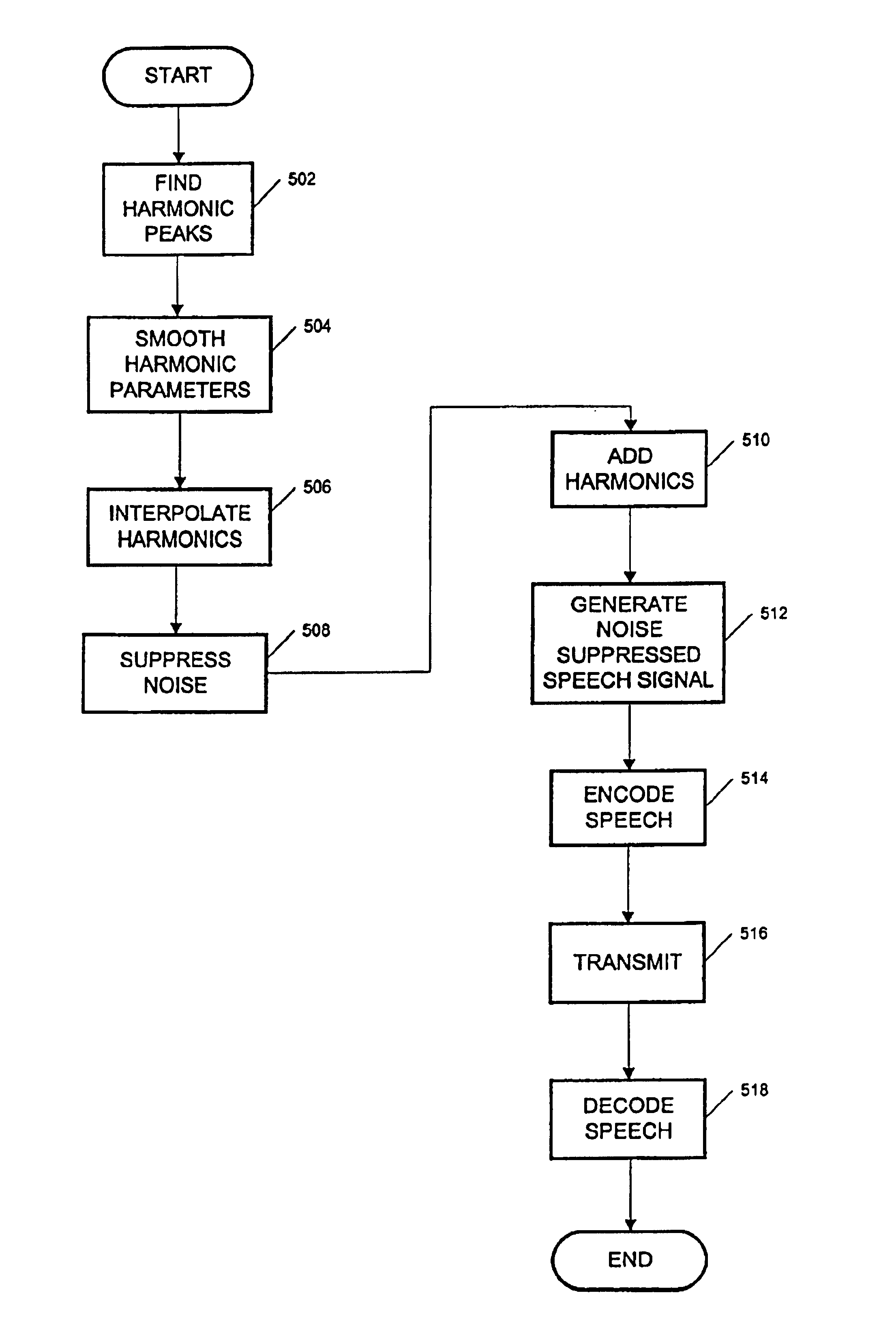
[0007]There is provided a speech encoder, comprising an encoding element for encoding a noise reduced speech signal, and a noise suppression element that takes a noisy speech signal and generates the noise reduced speech signal by maximizing the signal to noise ratio (SNR) of the noisy speech signal without significantly suppressing the speech components of the noisy speech signal. In one particular embodiment, the noise suppression element uses harmonic modeling techniques that maximizes the SNR in each sub-band of the noisy speech signal by reconstructing the noisy speech signal emphasizing harmonic frequencies within each sub-band. The SNR is further maximized eliminating noise components between harmonic peaks, and eliminating noise at harmonic peaks by smoothing harmonic parameters generated by the reconstruction of the noisy speech.

Problems solved by technology

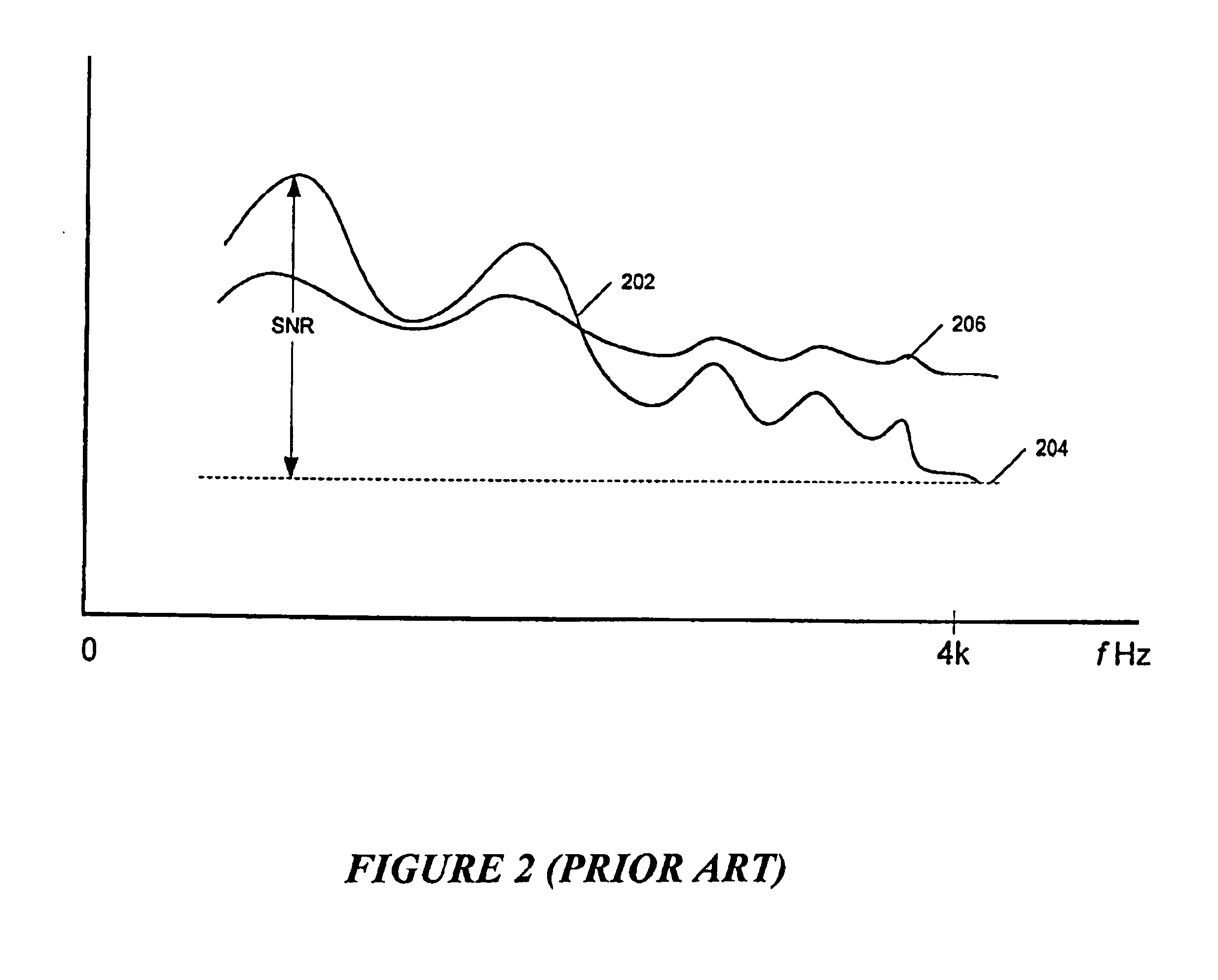
The flatness can create problems in that the signal-to-noise ratio (SNR), with regard to synthesized speech signal s′(n) (curve 202), may become too small for effective reproduction of speech signal s(n).
Traditional noise suppressors can reduce the background noise significantly, but they also distort the speech signal significantly due to the significant modification of the spectral envelope.
Therefore, the requirement for noise suppression and the requirement for perceptually natural voiced signals make it difficult to effectively achieve both simultaneously.

Method used


Image

  • Method and apparatus for improved noise reduction in a speech encoder
  • Method and apparatus for improved noise reduction in a speech encoder
  • Method and apparatus for improved noise reduction in a speech encoder

Examples


Embodiment Construction

[0023]FIG. 3 illustrates a speech coding system 300 in accordance with one embodiment of the invention. Speech coding system 300 comprises a noise suppression element 302, an encoder 304, a transmission channel 306, and a decoder 308. Noise suppression element 302 and encoder 304 form a modified speech encoder 310. Noise suppression element 302 takes a noisy speech signal ns(n) and produces a noise reduced speech signal ns′(n). The noise reduced speech signal ns′(n) is sent to encoder 304, which encodes ns′(n) and transmits encoding parameters to decoder 308 over transmission channel 306. For example, encoder 304 may be a linear predictive encoder, and decoder 308 may be a corresponding linear predictive decoder. In particular, encoder 304 may be a CELP encoder such as that disclosed in co-pending U.S. Application Ser. No. 09 / 625,088, titled “Method and Apparatus for Improving Weighting Filters in a CELP Encoder,” which is incorporated herein by reference in its entirety. Similarly,...


PUM


Abstract

A speech encoder comprises an encoding element for encoding a noise reduced speech signal, and a noise suppression element that takes a noisy speech signal and generates the noise reduced speech signal by maximizing the signal to noise ratio (SNR) of the noisy speech signal without suppressing the voiced speech components of the noisy speech signal. The noise suppression element may use harmonic modeling techniques that maximize the SNR in each sub-band of the noisy speech signal by reconstructing the voiced speech components of the noisy voiced speech signal emphasizing harmonic frequencies within each sub-band. The SNR is further maximized by eliminating noise components between signal peaks at the harmonic frequencies, and eliminating noise at signal peaks at the harmonic frequencies by smoothing harmonic parameters generated by the reconstruction of the voiced speech components of the noisy speech signal.

Description

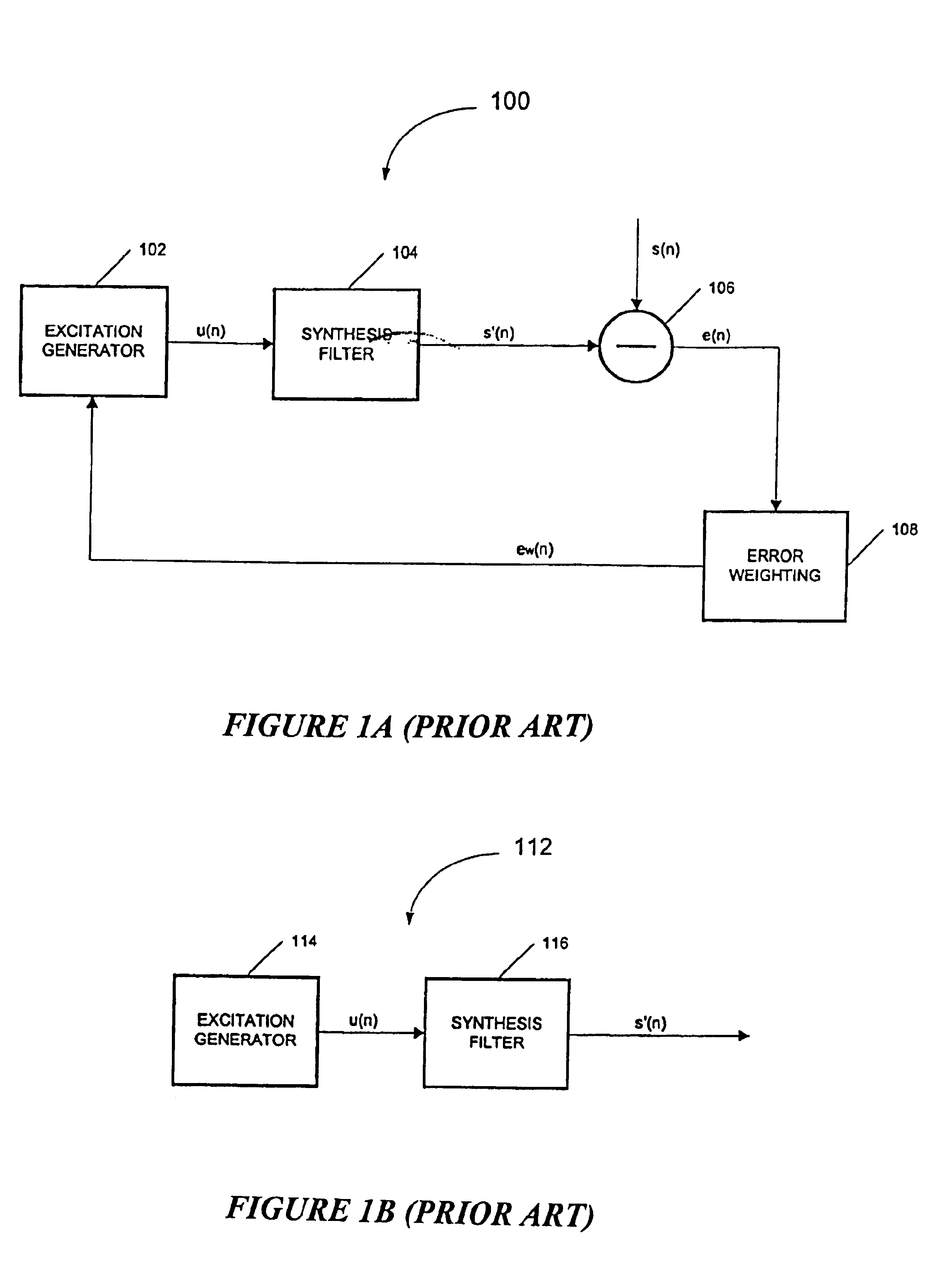
FIELD OF THE INVENTION[0001]The present invention relates generally to speech coding systems, and more particularly, to a method and apparatus for improved noise reduction in a speech encoder.BACKGROUND OF THE INVENTION[0002]In speech coding systems, reducing background noise in speech signals to improve the quality of processed speech is a primary endeavor. This fact is particularly true for lower signal to background noise ratios A typical speech coding system comprises an encoder, a transmission channel, and a decoder. Parameters for synthesizing speech signals are transmitted from the encoder over the transmission channel to the decoder. The decoder then uses the parameters to synthesize the desired speech signal.[0003]In wireless communications systems, the most common form of speech coders use linear predictive methods. One example linear predictive method is Code Excited Linear Prediction (CELP). A general diagram of a CELP encoder 100 is shown in FIG. 1A. A CELP encoder uses...

Claims


Application Information

Patent Timeline
IPC IPC(8): G10L21/00G10L21/02
CPCG10L21/0208
Inventor GAO, YANG
Owner WIAV SOLUTIONS LLC
Learn More