Fiber optic component marking with fiber optic indicia

a fiber optic and component technology, applied in the field of fiber optic communication, can solve problems such as the potential loss of optical power, and achieve the effect of efficient, accurate and reliabl

Inactive Publication Date: 2005-08-02
CORNING OPTICAL COMM LLC
View PDF18 Cites 6 Cited by
  • Summary
  • Abstract
  • Description
  • Claims
  • Application Information

AI Technical Summary

Benefits of technology

[0008]Among the objects of this invention is to provide efficient, accurate, and reliable production of fiber optic components marked with a fiber optic indicia that is associated with data on at least one of an optical characteristic and / or product characteristic of a fiber optic assembly. The method may further include using the fiber optic indicia to administer and to mate the fiber optic components. Another object of this invention is to provide the fiber optic components produced thereby. Further details on the objects, uses, advantages, and novel features of this invention are set forth below.

Problems solved by technology

Information about an optical characteristic of a ferrule is extremely important because when two optical fibers are connected by a ferrule connection, there exists a potential for loss of optical power due to an imperfect transfer of the fiber optic communication signal from one optical fiber to the other.

Method used


Image

  • Fiber optic component marking with fiber optic indicia
  • Fiber optic component marking with fiber optic indicia
  • Fiber optic component marking with fiber optic indicia

Examples


Embodiment Construction

[0021]This invention now will be described more fully hereinafter with reference to the accompanying drawings, in which several embodiments of the invention are shown. This invention may, however, be embodied in many different forms and should not be construed as limited to the embodiments set forth herein; rather, these embodiments are provided so that this disclosure will be thorough and complete, and will fully convey the scope of the invention to those skilled in the art. Like numbers refer to like elements throughout.

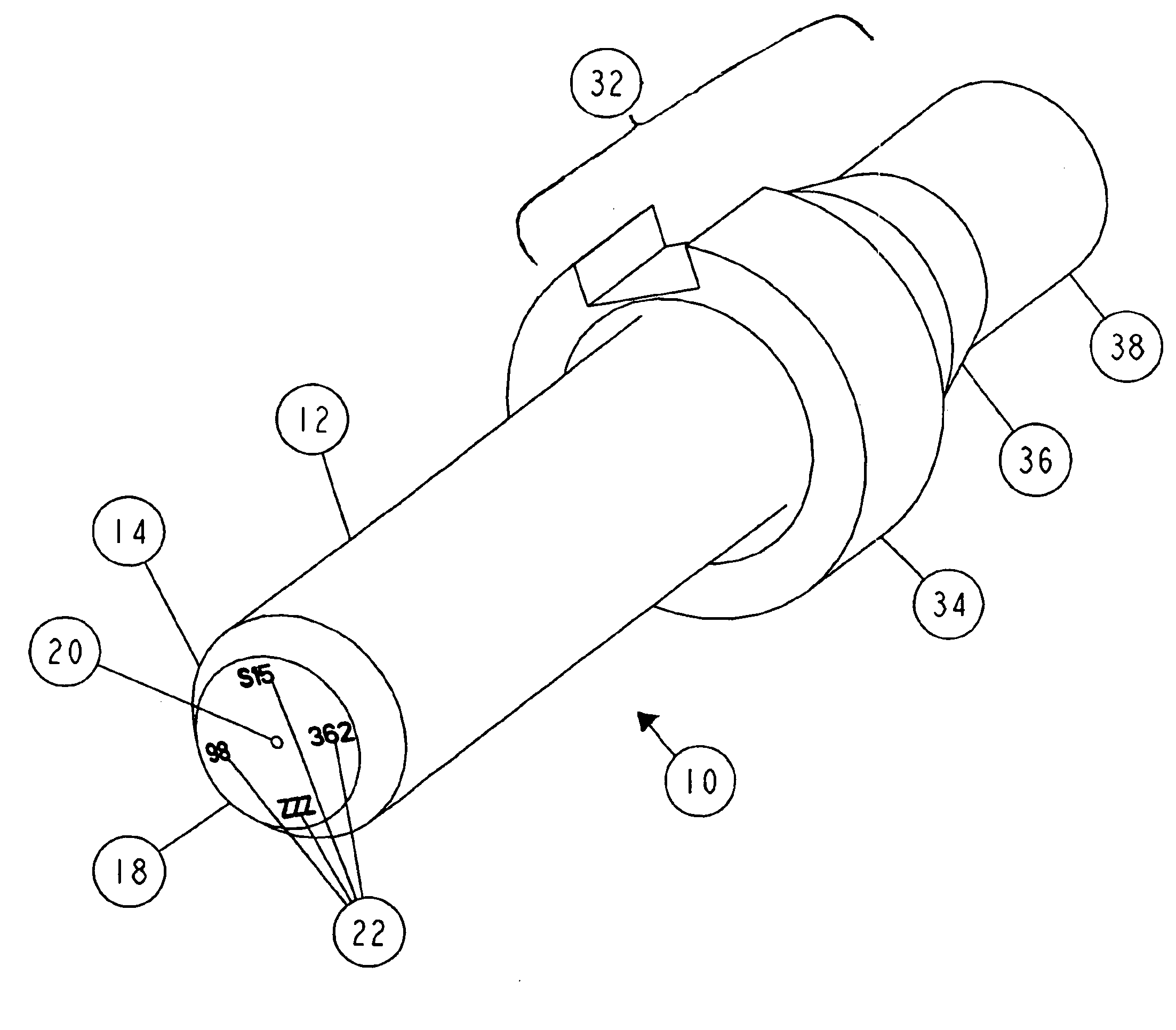
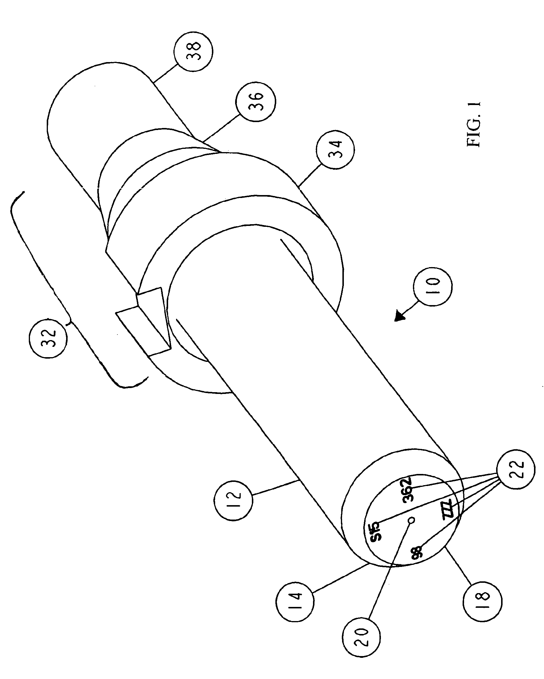
[0022]Referring to FIG. 1, a ferrule assembly 10 according to an embodiment of this invention is depicted. While the ferrule body 12 may be designed to mate with a variety of fiber optic assemblies, the ferrule assembly is advantageously designed to mate with a fiber optic connector, such as fiber optic connector 40 illustrated in FIGS. 4A and 4B and described in further detail in U.S. Pat. No. 6,030,129, entitled “Fiber Optic Connector And An Associated Method of ...


PUM


Abstract

This invention provides a method of marking a fiber optic indicia on the surface of a fiber optic component and the fiber optic component produced thereby. The fiber optic indicia is represented as a predetermined pattern marked on the fiber optic component and is associated with data about at least one of an optical characteristic and a product characteristic. According to a preferred embodiment, the fiber optic indicia is marked on a chamfered surface of a ferrule. The fiber optic indicia may include at least one alphanumerical character, a symbol, or combinations thereof. The method comprises establishing the predetermined pattern of the fiber optic indicia, providing a fiber optic component for marking, preparing a predetermined portion of a surface of the fiber optic component for marking, and marking the predetermined portion in accordance with the predetermined pattern of the fiber optic indicia.

Description

FIELD OF THE INVENTION[0001]This invention relates generally to the field of fiber optic communications. More particularly, this invention includes a method of marking a fiber optic indicia on a surface of a fiber optic component, such as a fiber optic ferrule and includes the apparatus produced thereby.BACKGROUND OF THE INVENTION[0002]Fiber optic communications has experienced explosive growth. In just a few years, the transmission of communication signals for voice, video, data, and the like has soared, and more growth is planned as fiber optic communication technology improves and networks expand to provide greater access.[0003]Inherent with any fiber optic network is the need to connect individual optical fibers to other optical fibers by using one of a multitude of fiber optic assemblies. The connection of these fiber optic assemblies must be executed with great care and precision in order to minimize losses in the transmitted communication signal. A common technique for connec...

Claims


Application Information

Patent Timeline
Patent Type & Authority Patents(United States)
IPC IPC(8): G02B6/38
CPCG02B6/3851G02B6/3869
Inventor FLEENOR, PAUL A.ROSSON, JOEL C.KNECHT, DENNIS M.
Owner CORNING OPTICAL COMM LLC
Why Eureka
Try Eureka