Eureka AIR delivers breakthrough ideas for toughest innovation challenges, trusted by R&D personnel around the world.

Visual interactive response system and method translated from interactive voice response for telephone utility

a telephone utility and interactive voice technology, applied in the field of telecommunications, can solve the problems of poor usability, system ubiquitousness, and general dislike of users of automatic telephone voice response systems

Inactive Publication Date: 2005-07-19
RPX CLEARINGHOUSE
View PDF12 Cites 309 Cited by
  • Summary
  • Abstract
  • Description
  • Claims
  • Application Information

AI Technical Summary

Problems solved by technology

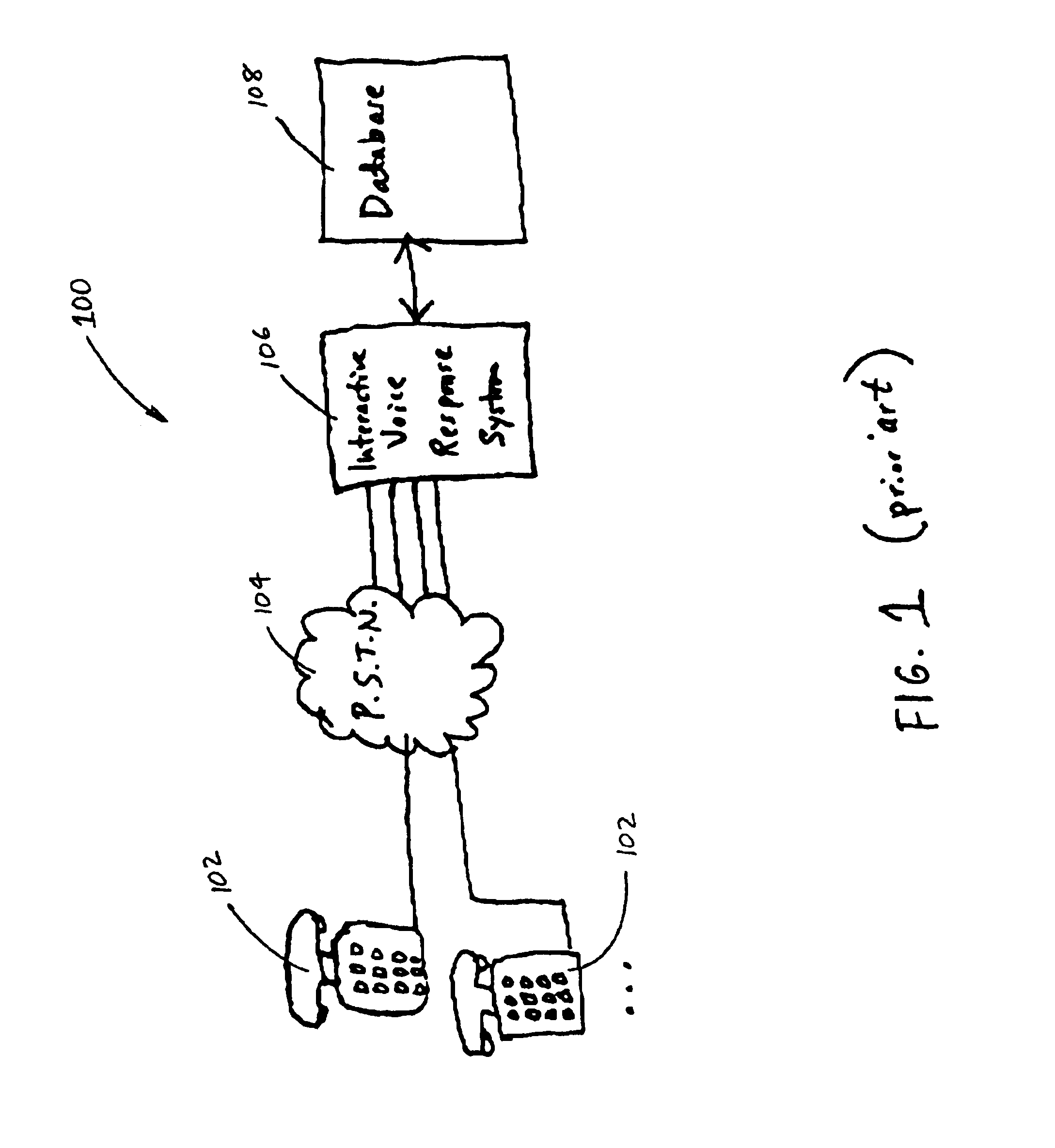
An undesirable characteristic of current automated telephone voice response systems (typically known as Interactive Voice Response, or IVR systems) is their poor usability.
These systems are ubiquitous but are generally disliked by users.
There are a variety of drawbacks relating to the poor usability of interactive voice response (IVR) systems.
Menus are often necessarily long because of the complexity of the different choices.
Often, users end up performing an extremely complex mental task, such as memorizing the menu items and corresponding responses while simultaneously trying to decide whether their problem fits, for example, in “Marketing” or “Sales”.
A problem of changing over to a visual-based telephone interactive system, however, is the very large installed based of interactive voice response (IVR) systems.
It will be very costly to manually convert these voice-based systems to visual-based systems that will work with display telephones.

Method used


Image

  • Visual interactive response system and method translated from interactive voice response for telephone utility
  • Visual interactive response system and method translated from interactive voice response for telephone utility
  • Visual interactive response system and method translated from interactive voice response for telephone utility

Examples


Embodiment Construction

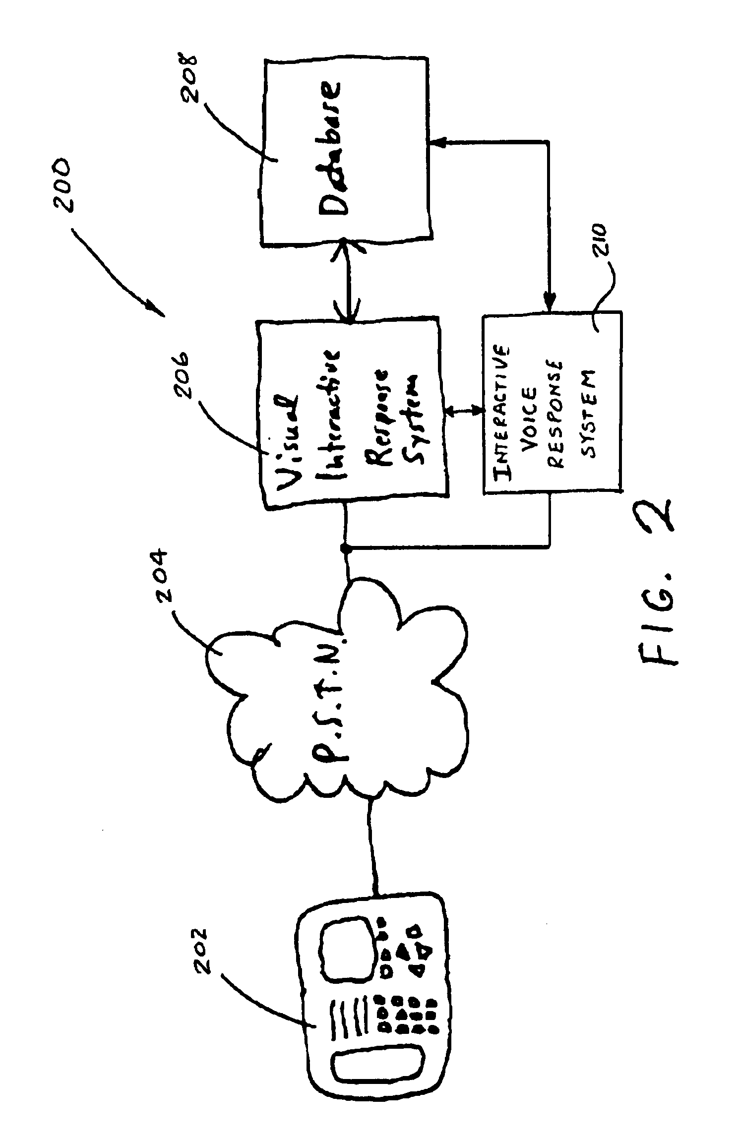
[0025]FIG. 2 illustrates a block diagram of an exemplary telecommunications system 200 using a visual interactive response (VIR) system in accordance with the invention. The telecommunications system 200 comprises a display telephone 202, a public switched telephone network (PSTN) 204, a visual interactive response (VIR) system 206 in accordance with the invention, and a database 208. With this system 200, a user using the display telephone 202 dials the telephone number associated with the visual interactive response (VIR) system 206 and connects thereto by way of the public switched telephone network (PSTN) 204. More specifically, the display telephone 202 is connected to a port on a computer system (e.g. a server) running the visual interactive response (VIR) system 206 that receives data from and transmits data to the display telephone 202 via an appropriate digital communications protocol, such as the Analog Display Services Interface (ADSI).

[0026]The ADSI protocol is based on ...


PUM


Abstract

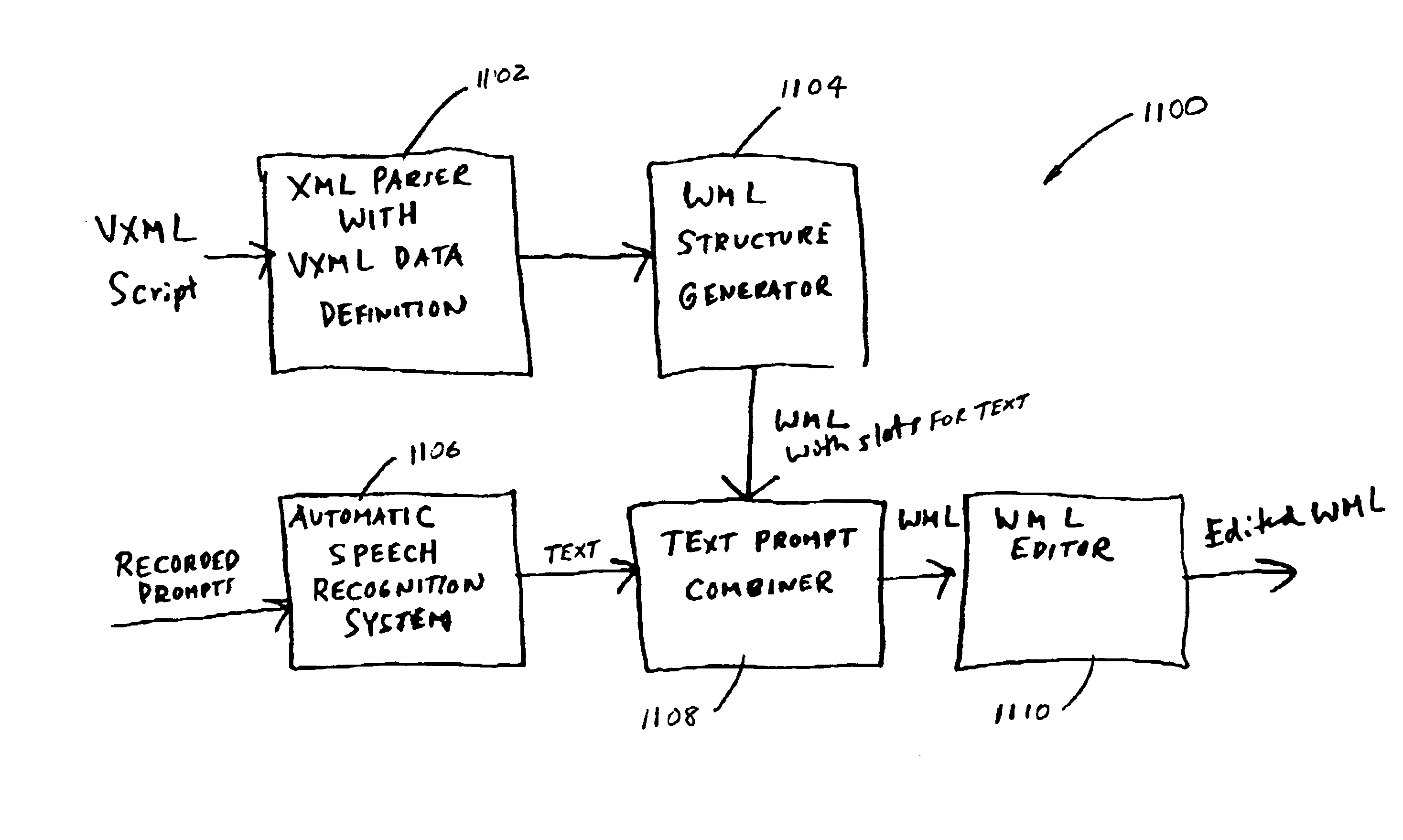
A system, method, and computer readable medium storing a software program for translating a script for an interactive voice response system to a script for a visual interactive response system. The visual interactive response system executes the translated visual-based script when a user using a display telephone calls the visual interactive response system. The visual interactive response system then transmits a visual menu to the display telephone to allow the user to select a desired response, which is subsequently sent back to the visual interactive response system for processing. The voice-based script may be defined in voice extensible markup language and the visual-based script may be defined in wireless markup language, hypertext markup language, or handheld device markup language. The translation system and program includes a parser for extracting command structures from the voice-based script, a visual-based structure generator for generating corresponding command structure for the visual-based script, a text prompt combiner for incorporating text translated from voice prompts into command structure generated by the structure generator, an automatic speech recognition routine for automatically converting voice prompts into translated text, and an editor for editing said visual-based script.

Description

FIELD OF THE INVENTION[0001]This invention relates generally to telecommunications, and in particular, to a system and method for deriving a visual interface response for a telephone set that has a display from an existing interactive voice response system.BACKGROUND OF THE INVENTION[0002]An undesirable characteristic of current automated telephone voice response systems (typically known as Interactive Voice Response, or IVR systems) is their poor usability. These systems are ubiquitous but are generally disliked by users. Companies that implement them are aware of this, but do it to save the considerable costs of having humans handle callers directly.[0003]There are a variety of drawbacks relating to the poor usability of interactive voice response (IVR) systems. Most result from the use of voice as a media. Typically, users have to listen to a series of voice menus (e.g., “Press 1 to speak with Marketing, Press 2 for Sales, Press 3 for Finance . . .”). Menus are often necessarily ...

Claims


Application Information

Patent Timeline
IPC IPC(8): G10L15/00G10L15/26H04M3/493
CPCH04M3/493H04M3/4938H04M7/0036H04M2201/42H04M2201/60
Inventor WILL, CRAIG A.SHELLEY, WAYNE N.
Owner RPX CLEARINGHOUSE
Why Eureka
Eureka Blog
Learn More