Optical disk drive that supports a plurality of recording speeds

Inactive Publication Date: 2005-07-19
KK TOSHIBA
View PDF8 Cites 13 Cited by
  • Summary
  • Abstract
  • Description
  • Claims
  • Application Information

AI Technical Summary

Benefits of technology

[0009]In order to solve the above problems and to achieve the above object, an optical disk drive, recording

Problems solved by technology

The number of types of recording speeds that the optical disk device can support is limited.
In order to support more recording speeds, the cost of the optical disk device increases unwantedly.
Likewise, in order to support more recording interrupt factors, control becomes complicated, resulting in high cost of the optical disk device.

Method used


Image

  • Optical disk drive that supports a plurality of recording speeds
  • Optical disk drive that supports a plurality of recording speeds
  • Optical disk drive that supports a plurality of recording speeds

Examples


Embodiment Construction

[0024]An embodiment of the present invention will be described hereinafter with reference to the accompanying drawings.

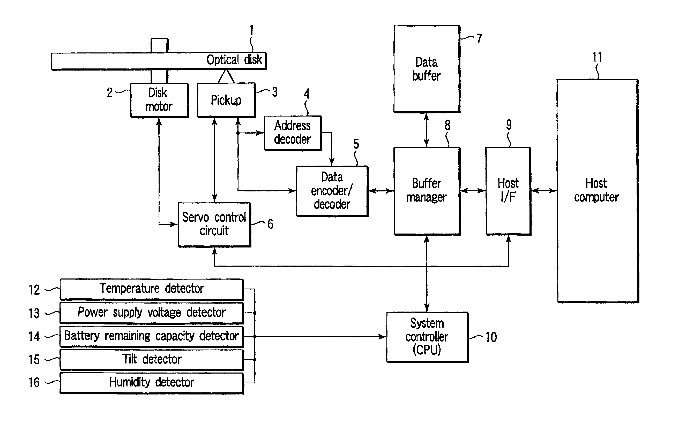
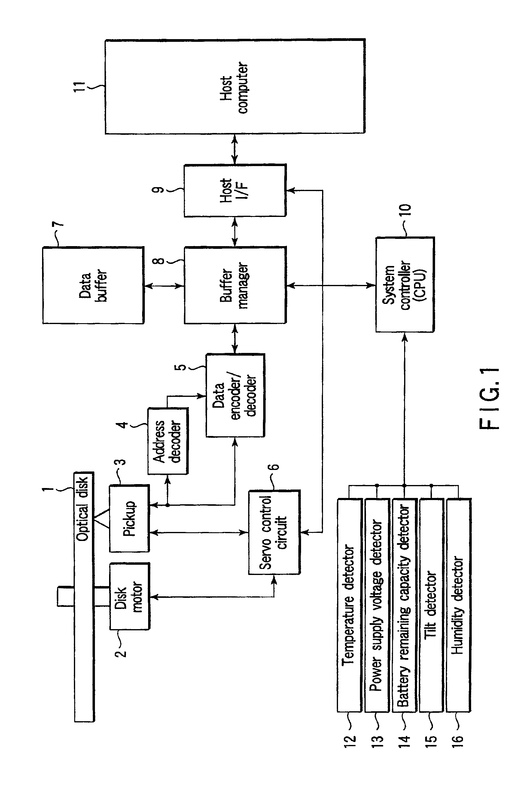
[0025]FIG. 1 is a schematic diagram of an optical disk device according to an embodiment of the present invention. This optical disk device records data on an optical disk 1 and reproduces data recorded thereon. As shown in FIG. 1, the optical disk device comprises a disk motor 2, pickup 3, address decoder 4, data encoder / decoder 5, servo control circuit 6, data buffer 7, buffer manager 8, host I / F 9, system controller (CPU) 10, temperature detector 12, power supply voltage detector 13, battery remaining capacity detector 14, tilt detector 15, and humidity detector 16.

[0026]The disk motor 2 rotates the optical disk 1 at a predetermined speed. Driving of the disk motor 2 is controlled by the servo control circuit 6. The pickup 3 irradiates the optical disk 1 with a recording light beam to record objective data on the optical disk 1. Furthermore, the pickup 3 irradiat...


PUM


Abstract

A buffer underrun is generated intentionally, and the apparent recording speed is changed by alternately repeating start and stop of recording by using the buffer underrun free recording function to obtain a desired recording speed.

Description

CROSS-REFERENCE TO RELATED APPLICATIONS[0001]This application is based upon and claims the benefit of priority from the prior Japanese Patent Application No. 2001-174425, filed Jun. 8, 2001, the entire contents of which are incorporated herein by reference.BACKGROUND OF THE INVENTION[0002]1. Field of the Invention[0003]The present invention relates to an optical disk drive for recording data on an optical disk. More specifically, the present invention relates to recording speed control in this optical disk drive, and measures to be taken upon generation of recording interrupt factors.[0004]2. Description of the Related Art[0005]In general, an optical disk device supports one or a plurality of recording speeds (double (×2)-speed, quadruple (×4)-speed, octuple (×8)-speed, and the like), and can record data at the supported recording speeds.[0006]The optical disk device assumes various recording interrupt factors upon design, and can interrupt recording operation in correspondence with...

Claims


Application Information

Patent Timeline
IPC IPC(8): G11B20/10G11B27/36G11B19/04G11B7/0045G11B7/00G11B19/00G11B19/28
CPCG11B19/04G11B20/10G11B27/36G11B7/0045G11B2020/10814G11B2220/20
Inventor KOMAKI, SHIGERU
Owner KK TOSHIBA
Why Eureka
Try Eureka