
Method and system for reducing undesirable cross talk in diagnostic ultrasound arrays

a diagnostic ultrasound and array technology, applied in the field of methods and systems for reducing undesirable cross talk in diagnostic ultrasound arrays, can solve problems such as degraded image, delayed cross talk signal, and beam distortion

Inactive Publication Date: 2005-07-19
SIEMENS MEDICAL SOLUTIONS USA INC
View PDF17 Cites 27 Cited by
  • Summary
  • Abstract
  • Description
  • Claims
  • Application Information

AI Technical Summary

Benefits of technology

[0010]In fact, cross coupling is only significant on a few neighboring elements. In the case below, cross coupling is limited to two elements on each side of the element being excited. (However, this is not a limitation here—the full matrix encompassing all crosstalk terms is considered if desired.) The matrix becomes a banded matrix with band width 5. All other values of H are 0. This simplifies the characterization of the H matrix and allows for more efficient matrix solution.
[0026]Exemplary advantages include the following, but are not limited thereto: Improved image quality—spatial resolution and contrast quality; Potentially, reduced cost; and potentially, improved reliability.

Problems solved by technology

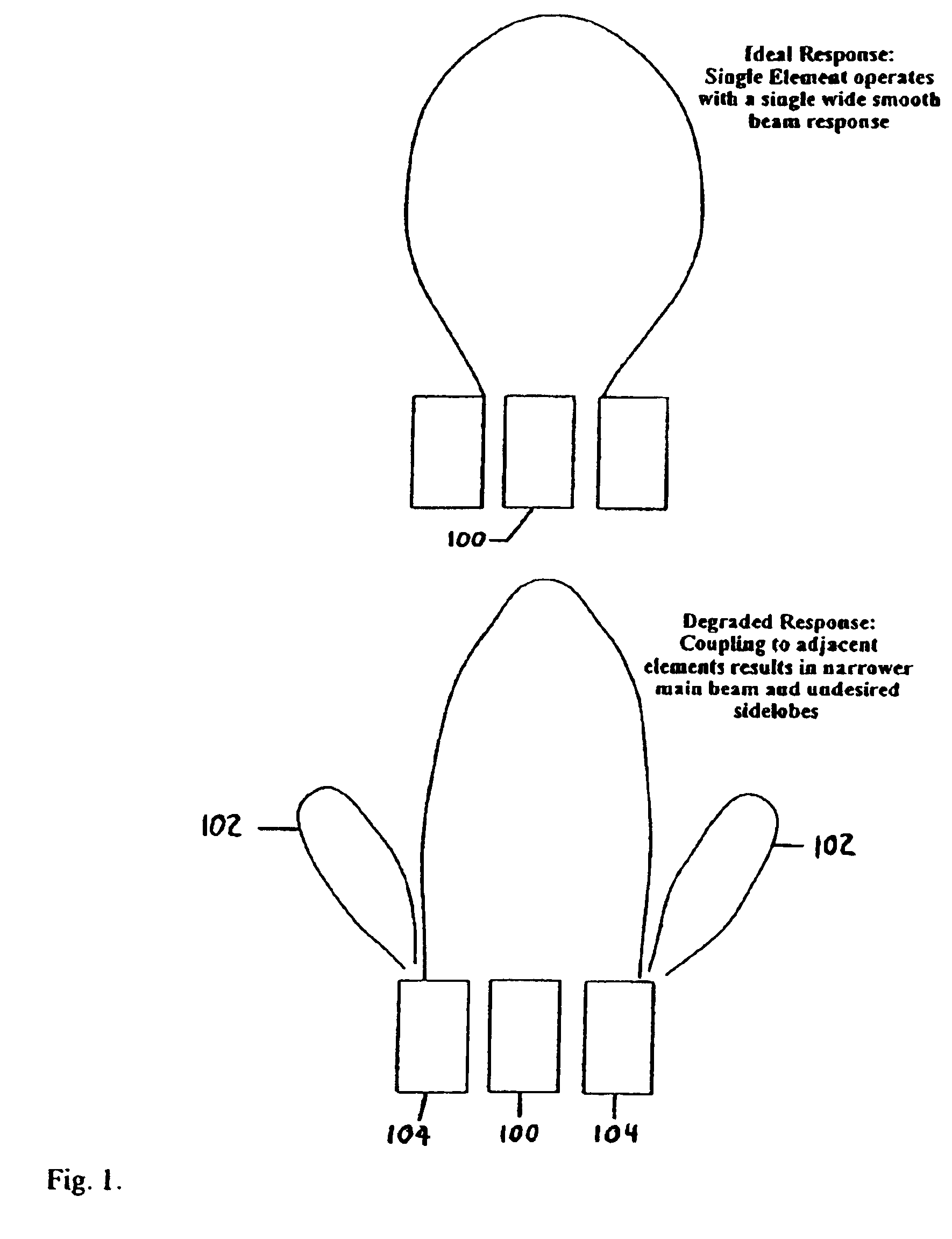
If they do not operate independently—i.e. there is ‘cross talk’—then the beam is distorted and a degraded image results.
Generally, electrical cross talk is instantaneous and acoustic cross talk results in a delayed cross talk signal due to the much slower propagation velocity of acoustic waves versus electromagnetic / electrostatic coupling.

Method used


Image

  • Method and system for reducing undesirable cross talk in diagnostic ultrasound arrays
  • Method and system for reducing undesirable cross talk in diagnostic ultrasound arrays
  • Method and system for reducing undesirable cross talk in diagnostic ultrasound arrays

Examples


Embodiment Construction

Transmit Mode

[0065]Each array element is excited by an electrical waveform. Historically these waveforms were simple in form—impulses, steps or square wave bursts. However, the current state of the art is to use a programmable waveform. The major driving factor for this is the desire to reduce transmitted harmonic signals since it is now current practice to form the received signal image at the second harmonic of the transmitted signal since the second harmonic signal gives rise to a far higher quality image. This imaging technique is typically referred to as ‘Tissue Harmonic Imaging’. The significance of the need to reduce the transmitted second harmonic is that it is preferable to program the shape of the transmitted waveform using some form of digital waveform encoding that is fed into a D->A converter prior to amplification. Patents describing this technique in detail include Cole U.S. Pat. No. 5,675,554 and Hossack U.S. Pat. No. 5,740,128. (both of which are hereby incorporated...


PUM


Abstract

Practical diagnostic ultrasound arrays invariably exhibit a degree of unwanted inter-element cross coupling or cross talk. This results in degraded beam performance that in turn results in degraded image resolution (spatial resolution and contrast performance). Current approaches to reducing inter element coupling may be costly and may make the transducer array fragile. There is a need to overcome the cross talk problem with minimal expense and impact on reliability. The approach taken here overcomes a substantial component of the cross talk with minimal expense. The approach is versatile and has applicability in both transmit and receive. The approach improves image resolution. This technique has particular applicability in the field of silicon substrate based MEMS transducers in which the continuous, low loss, silicon wafer substrate gives rise to significant unwanted cross talk.

Description

BACKGROUND[0001]Diagnostic Ultrasound is one of the most versatile, lowest cost and widely used diagnostic imaging modalities in use today. These systems have a controller that controls transmit and receive functions. The conversion of electrical energy to acoustic energy and vice versa is performed by a transducer array in which individual adjacent elements are separately phased in transmit and receive in order to focus the acoustic beam at discrete spatial locations. In the ideal ultrasonic array, the adjacent elements operate entirely independently of each other. If they do not operate independently—i.e. there is ‘cross talk’—then the beam is distorted and a degraded image results. The cross talk can have its origin in either electrical (capacitive) cross talk or acoustic propagation cross talk. Generally, electrical cross talk is instantaneous and acoustic cross talk results in a delayed cross talk signal due to the much slower propagation velocity of acoustic waves versus elect...

Claims


Application Information

Patent Timeline
Patent Type & Authority Patents(United States)
IPC IPC(8): A61B8/00A61B8/06B06B1/02B06B1/06G01H11/06G10K11/34
CPCB06B1/0292B06B1/0622G01H11/06G10K11/346
Inventor HOSSACK, JOHN A.WOICIK, GREGORY L.
Owner SIEMENS MEDICAL SOLUTIONS USA INC
Learn More