
Leveling apparatus for vehicle headlamp

a leveling apparatus and headlamp technology, applied in the field of new headlamp leveling apparatus, can solve the problems of affecting the leveling effect of the headlamp,

Inactive Publication Date: 2005-07-19
KOITO MFG CO LTD
View PDF4 Cites 7 Cited by
  • Summary
  • Abstract
  • Description
  • Claims
  • Application Information

AI Technical Summary

Benefits of technology

The present invention is a leveling apparatus that has thread ridges on its sides. These thread ridges are formed by one to two pitches, which means they always fit together. This design prevents the leveling apparatus from being affected by changes in temperature and humidity.

Problems solved by technology

A problem with the conventional leveling apparatus a for a vehicle headlamp as described above arises from the fact that because the thread ridges m of the worm wheel d together with the thread ridges n of the shaft h are formed over several pitches, generally over the range of five to eight pitches (see FIG.
However, a backlash is produced between the two members when the play is too large and the positional accuracy may deteriorate.
Notwithstanding, if the play is set too small with the thread ridges m and n on two sides staying in mesh over several pitches with their dimensions growing greater as the temperature rises, an accumulation of dimensional errors produced therebetween results in tightening the intermeshing of the thread ridges m and n on two sides (see FIG.
This problem appears notable particularly when the worm wheel d and the shaft h are made of resin materials.
If errors in pitch are produced between the thread ridges m and n on two sides, error accumulates as the number of pitches meshing together grows larger.
The problem in this case is that the required torque increases.

Method used


Image

  • Leveling apparatus for vehicle headlamp
  • Leveling apparatus for vehicle headlamp
  • Leveling apparatus for vehicle headlamp

Examples


first embodiment

[0050]FIG. 5 shows another example of the invention.

[0051]This example is different from the above first embodiment of the invention in that a worm wheel is used as a member with thread ridges formed by one to two pitches. As for the rest, both the embodiments thereof are similar in arrangement. Therefore, only the different features will be described in detail with illustration.

[0052]Thread ridges 15Aa by one to two pitches are formed inside the tapped hole 15A of a worm wheel 13A.

[0053]Thread ridges 18Aa are formed on the outer peripheral face of the driven portion 18A of a shaft 10A, the thread ridges 18Aa being formed over several pitches, for example, at five to eight pitches.

[0054]Also in this example of the leveling apparatus, because the thread ridges 15Aa formed on the worm wheel 13A and the thread ridges 18Aa formed on the shaft 10A always mesh together by one to two pitches, an accumulation of dimensional errors because of changes in temperature, humidity and so forth doe...

second embodiment

[0058]Also in the leveling apparatus 25 according to the invention, because the thread ridges 15a formed on the worm wheel 13 and the thread ridges 26a formed on the shaft 26 always mesh together by one to two pitches, an accumulation of dimensional errors because of changes in temperature, humidity and so forth does not affect the leveling apparatus. Furthermore, even though play between the two thread ridges 15a and 26a is decreased as much as possible, smooth operation is not impeded by changes in temperature, humidity and so forth.

[0059]FIG. 7 shows another example of the second embodiment of the invention. This example is different from the above second embodiment of the invention in that a worm wheel is used as a member with thread ridges formed by one to two pitches. As for the rest, this example is similar in arrangement to the second or first embodiments. Only the different features will be described in detail with illustration.

[0060]The thread ridges 15Aa by one to two pit...


PUM


Abstract

A leveling apparatus for a vehicle headlamp has a case body, a motor disposed within the case body, a worm wheel supported by the case body rotatably but unmovably in the longitudinal direction and rotated by the motor and a shaft screwed into the worm wheel. The shaft and the worm wheel are screwed together by thread ridges provided on the inner side of the worm wheel and thread ridges provided on the outer periphery of a driven portion forming the shaft. The thread ridges on one side out of the thread ridges on two sides are formed by one to two pitches.

Description

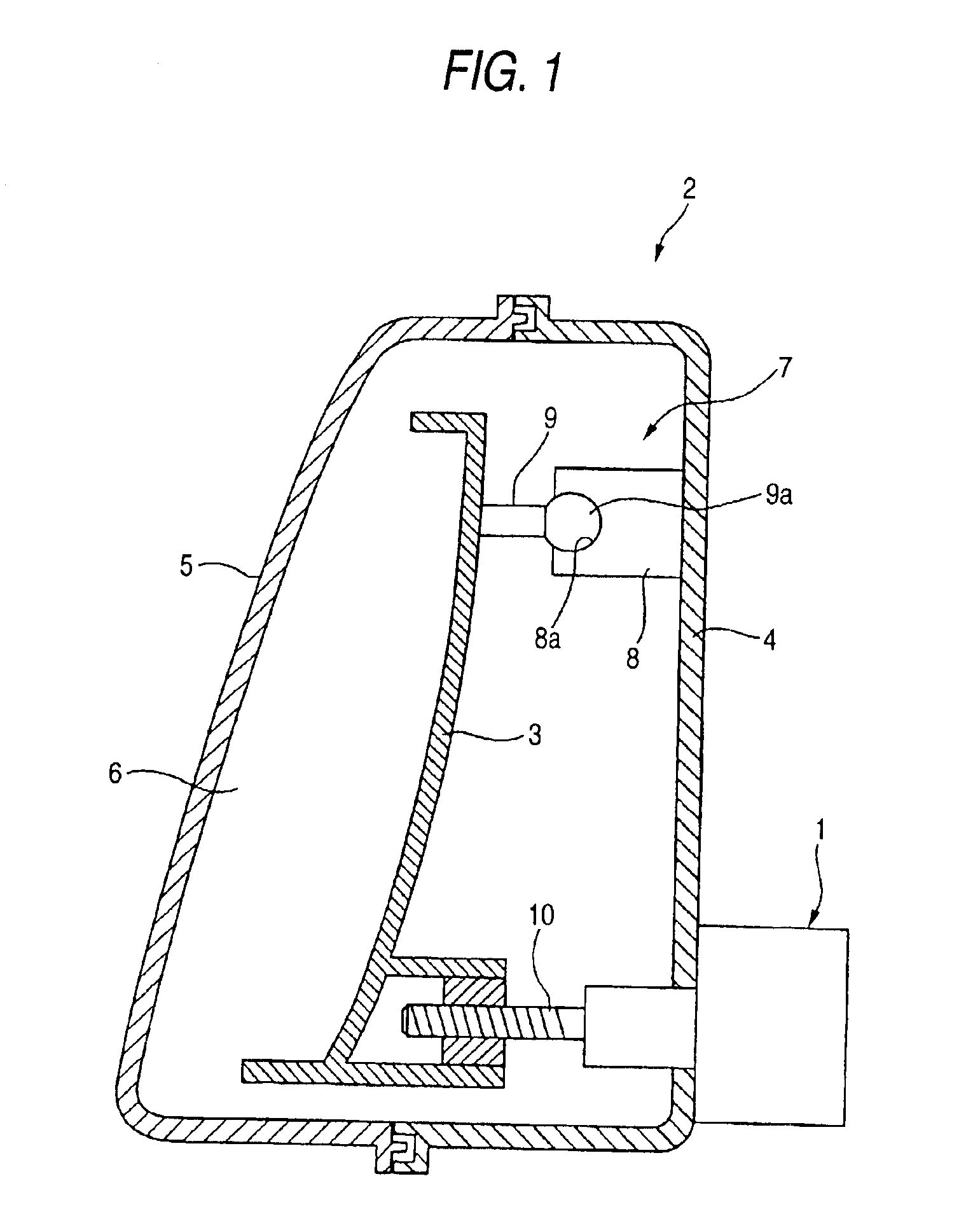
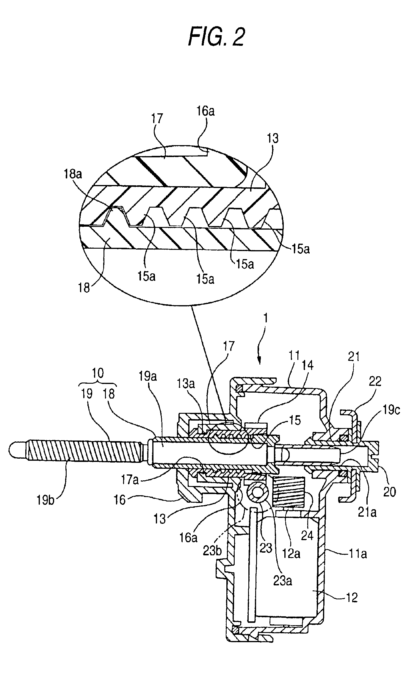
BACKGROUND OF THE INVENTION[0001]1. Field of the Invention[0002]The present invention relates to a novel leveling apparatus for a vehicle headlamp. More particularly, the present invention relates to providing a leveling apparatus unaffected by ambient temperature and ambient humidity.[0003]2. Description of the Related Art[0004]A leveling apparatus is provided with a drive source such as a motor, which may be remotely controlled by a driver or automatically driven. When driving the drive source, a tiltable member for changing the direction of irradiation of the headlamp, such as a reflector supporting a light source or a lamp body containing the light source and the reflector, is tilted.[0005]FIGS. 8 and 9 show an example of a conventional leveling apparatus for a vehicle headlamp.[0006]A leveling apparatus has a case body b in which a motor c is contained. A worm wheel d is disposed within the case body b rotatably but unmovably in the longitudinal direction and a tapped hole e is...

Claims


Application Information

Patent Timeline
Patent Type & Authority Patents(United States)
IPC IPC(8): G01M11/06F16H25/18B60Q1/076F21S8/10F21V7/16F21V14/04F21W101/10
CPCB60Q1/076G01M11/062
Inventor DEGUCHI, HIROHISA
Owner KOITO MFG CO LTD
Learn More