
Wide passband optical interleaver

a wide-passband, optical interleaver technology, applied in the field of wdm and dwdm communication systems, can solve the problems of falling off (i.e., the slope of the passband sidewall) and high cost for parties

Inactive Publication Date: 2005-07-12
WAVESPLITTER TECH INC
View PDF11 Cites 6 Cited by
  • Summary
  • Abstract
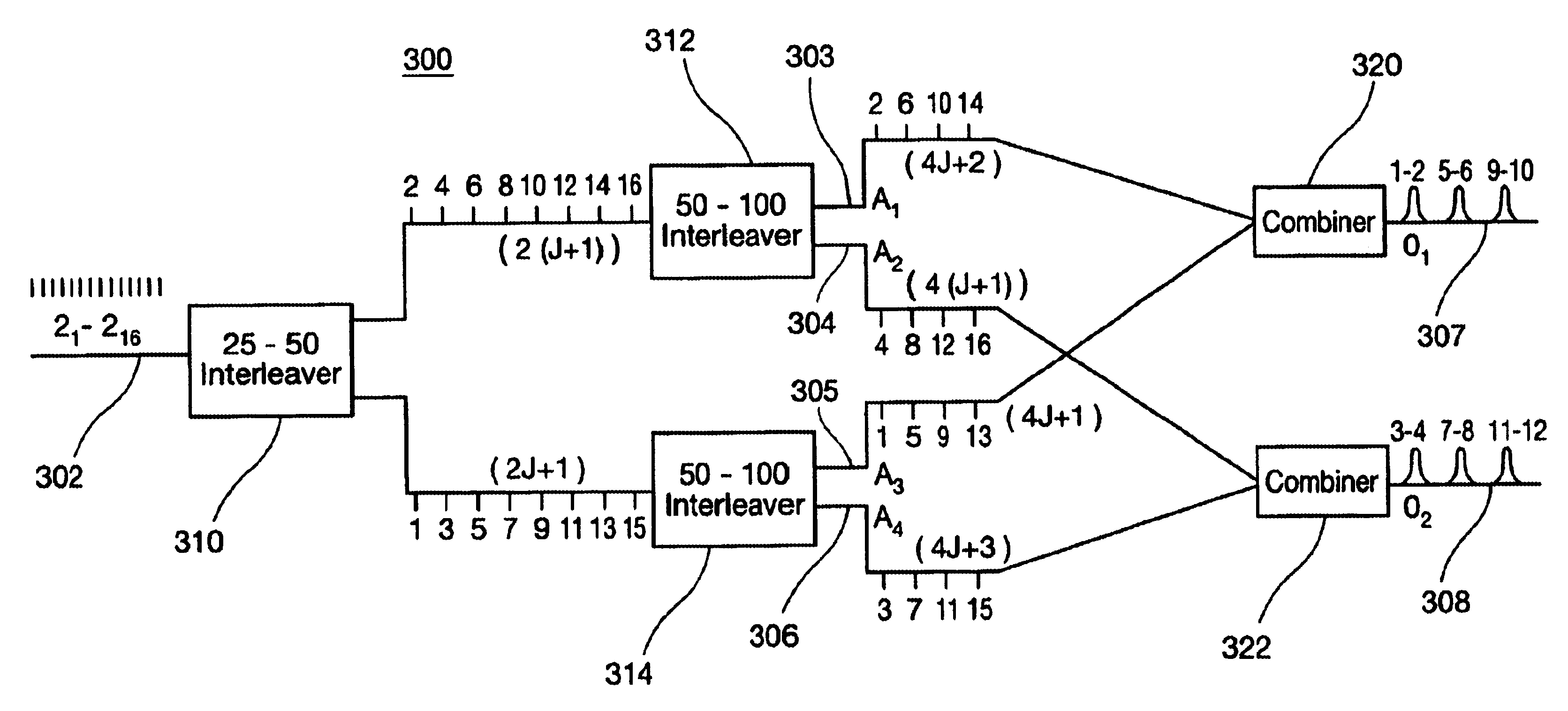
  • Description
  • Claims
  • Application Information

AI Technical Summary

Benefits of technology

[0007]In accordance with the present invention, a method and apparatus are provided for reformatting a WDM signal that includes a plurality of optical channels having a first bandwidth and a first channel spacing. An important advantage of the present invention is that it provides an interleaver arrangement in which the ratio of the passband width relative to the channel spacing is approximately doubled.
[0008]The method begins by receiving the WDM signal and dividing it into first and second subsets of optical channels each having a second channel spacing. Next, the first subset of optical channels are divided into third and fourth subsets of optical channels each having a third channel spacing. In addition, the second subset of optical channels is divided into fifth and sixth subsets of optical channels each having a fourth channel spacing. The third and fifth subsets of optical channels are combined to generate a first output WDM signal, while the fourth and sixth subsets of optical channels are combined to generate a second output WDM signal.
[0009]In accordance with one aspect of the invention, the first and second subsets of optical channels are even and odd channels, respectively, of the plurality of optical channels of the WDM signal. Likewise, the third and fourth subsets of optical channels may be even and odd channels, respectively, of the first subset of optical channels, whereas the fifth and six subsets of optical channels may be even and odd channels, respectively, of the second subset of optical channels.
[0010]In accordance with another aspect of the invention, the second channel spacing is approximately equal to twice the first channel spacing. Also, the third and fourth channel spacings are approximately equal to twice the second channel spacing.
[0011]In accordance with another aspect of the invention, an interleaver arrangement is provided. The arrangement includes an input interleaver having an input port and at least a pair of output ports and a second interleaver having a second input port coupled to a first of the two output ports of the input interleaver. The second interleaver also has at least a second pair of output ports. The arrangement also includes a third interleaver having a third input port coupled to a second of the two output ports of the input interleaver. The third interleaver also has at least a third pair of output ports. A first optical combiner has a first combiner input port coupled to a first of the second pair of output ports of the second interleaver. The first optical combiner also has a second combiner input port coupled to a first of the third pair of output ports of the third interleaver. A second optical combiner has third and fourth combiner input ports and a second combiner output port. The third combiner input port is coupled to a second of the second pair of output ports of the second interleaver. The fourth combiner input port is coupled to a second of the third pair of output ports of the third interleaver.
[0012]In accordance with another aspect of the invention, the input interleaver is configured to receive on the input port a WDM signal that includes a plurality of optical channels having a first bandwidth and a first channel spacing and to divide the WDM signal into first and second subsets of optical channels each having a second channel spacing. Likewise, the second interleaver may be configured to receive on the second input port the first subset of optical channels and to divide the first subset of optical channels into third and fourth subsets of optical channels each having a third channel spacing. The third interleaver may be configured to receive on the third input port the second subset of optical channels and to divide the second subset of optical channels into fifth and sixth subsets of optical channels each having a fourth channel spacing.

Problems solved by technology

This upgrade requirement can be very expensive for parties with an extensive amount of fiber optic equipment that is already deployed.
Unfortunately, when the passband of a conventional interleaver is increased, the fall-off (i.e., the slope of the passband sidewalls) also increases.

Method used


Image

  • Wide passband optical interleaver
  • Wide passband optical interleaver
  • Wide passband optical interleaver

Examples


Embodiment Construction

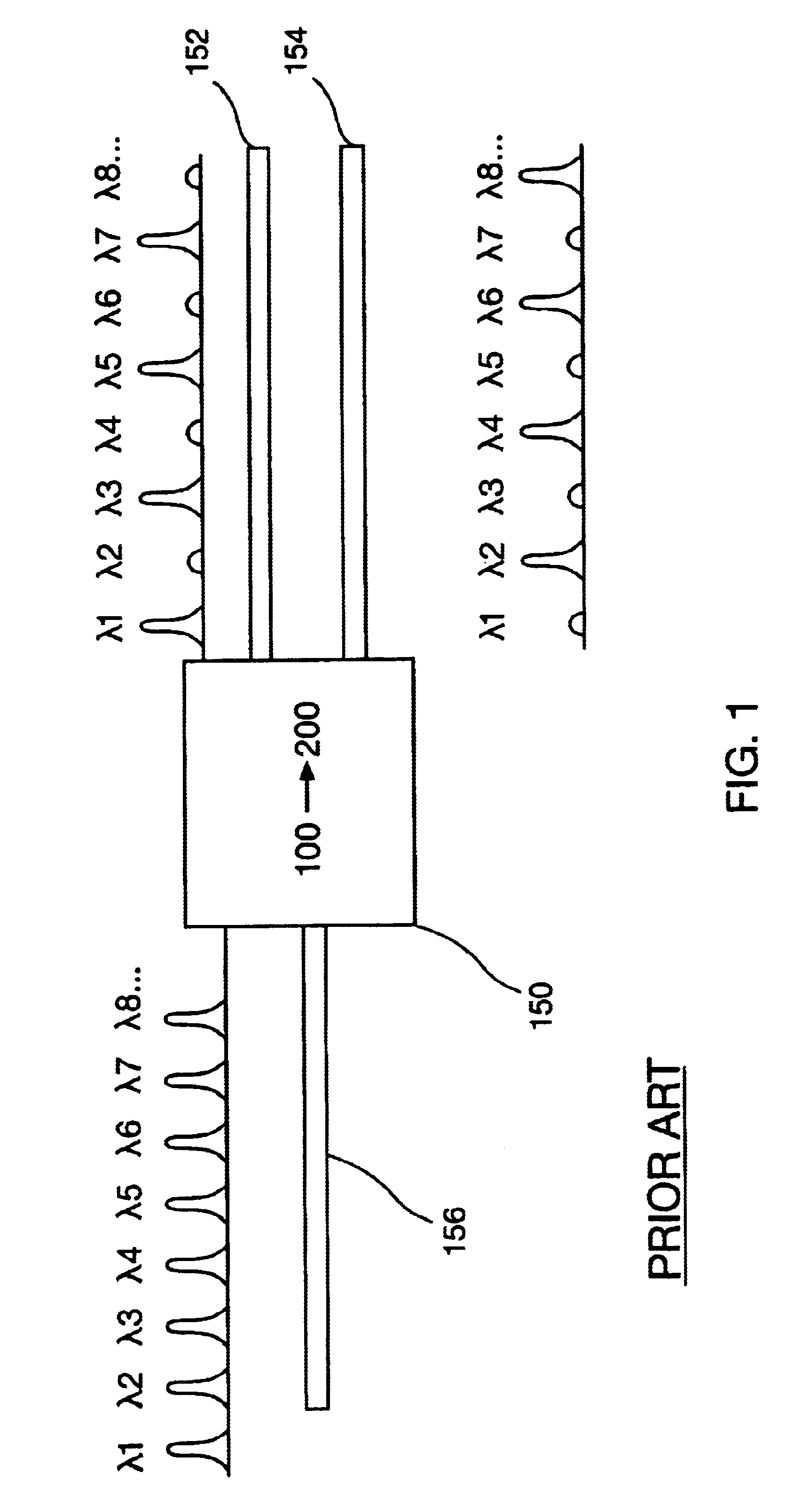
[0019]FIG. 1 illustrates the functionality of a conventional single-stage 1×2 optical interleaver. As shown, interleaver 150 receives on input port 156 a WDM optical signal having a channel spacing of 100 GHz and converts it two signals each having a channel spacing of 200 GHz, which are directed to output ports 152 and 154. While the device shown in FIG. 1 can function as both an interleaver and a deinterleaver, it will generally be referred to simply as an interleaver. The deinterleaver separates a subsets of channels. The interleaver mixes subsets of channels. In this example, when functioning as a deinterleaver, the odd channels have a 200 GHz spacing and the even channels have a 200 GHz spacing. When functioning as an interleaver, the even and odd channels having 200 GHz spacing are combined into a signal stream having 100 GHz signal spacing. Similar interleaving can be provided to convert between 50 GHz spaced channels and 100 GHz spaced channels, as well as between other sets...


PUM


Abstract

A method and apparatus is provided for reformatting or interleaving a WDM signal that includes a plurality of optical channels having a first bandwidth and a first channel spacing. The method begins by receiving the WDM signal and dividing it into first and second subsets of optical channels each having a second channel spacing. Next, the first subset of optical channels are divided into third and fourth subsets of optical channels each having a third channel spacing. In addition, the second subset of optical channels is divided into fifth and sixth subsets of optical channels each having a fourth channel spacing. The third and fifth subsets of optical channels are combined to generate a first output WDM signal, while the fourth and sixth subsets of optical channels are combined to generate a second output WDM signal.

Description

FIELD OF THE INVENTION[0001]The present invention relates generally to WDM and DWDM communication systems, and more generally to an optical interleaver employed in such systems.BACKGROUND OF THE INVENTION[0002]Optical wavelength division multiplexing (WDM) and dense wavelength division multiplexing (DWDM) have gradually become the standard backbone networks for fiber optic communication systems. WDM and DWDM systems employ signals consisting of a number of different wavelength optical signals, known as carrier signals or channels, to transmit information on optical fibers. Each carrier signal is modulated by one or more information signals. As a result, a significant number of information signals may be transmitted over a single optical fiber using WDM and DWDM technology.[0003]One approach to increasing fiber optic capacity is to use more closely spaced channels. For example, at one point in time, 200 GHz spacing was common for optical channels. At that time optical components were...

Claims


Application Information

Patent Timeline
Patent Type & Authority Patents(United States)
IPC IPC(8): H04J14/02G02B6/34
CPCG02B6/29361G02B6/29386H04J14/02
Inventor LI, YUAN P.WANG, YANSHINE, JR., ROBERT JOHNSULLIVAN, KEVIN
Owner WAVESPLITTER TECH INC
Learn More