
Cover locking/unlocking mechanism and a printer having the cover locking/unlocking mechanism

a locking/unlocking mechanism and printer technology, applied in mechanical devices, colloidal chemistry, breathing protection, etc., can solve the problems of easy and undesirable opening of the cover, and achieve the effect of preventing the play of the paper feed roller

Active Publication Date: 2005-07-12
SEIKO EPSON CORP
View PDF17 Cites 17 Cited by
  • Summary
  • Abstract
  • Description
  • Claims
  • Application Information

AI Technical Summary

Benefits of technology

The present invention provides a locking and unlocking mechanism for a cover of a device. The mechanism includes a cover-side engaging part, a body-side engaging part, a cover lifting part, a manual operating member, and a locking lever. The manual operating member is a cover-side engaging part that can be opened and closed by sliding the locking lever. The locking lever can also swing between a locked position and an unlocked position. The mechanism ensures that the cover can be easily opened and closed with a single operation. The locking lever is slidably supported at two places, and a curved guide hole and curved pin guide hole are formed to guide the locking lever. The link pin and contact part enable the locking lever to pivot centered on the first guide pin. The mechanism also allows for easy closing of the cover by sliding the locking lever to the unlocked position.

Problems solved by technology

This is inconvenient because the cover cannot be opened with a single operation.
However, when these operations are linked and the lock is unintentionally released by vibration or impact, the cover is easily and undesirably opened.

Method used


Image

  • Cover locking/unlocking mechanism and a printer having the cover locking/unlocking mechanism
  • Cover locking/unlocking mechanism and a printer having the cover locking/unlocking mechanism
  • Cover locking/unlocking mechanism and a printer having the cover locking/unlocking mechanism

Examples


Embodiment Construction

[0038]Preferred embodiments of the present invention are described below with reference to the accompanying figures.

[0039]General Configuration

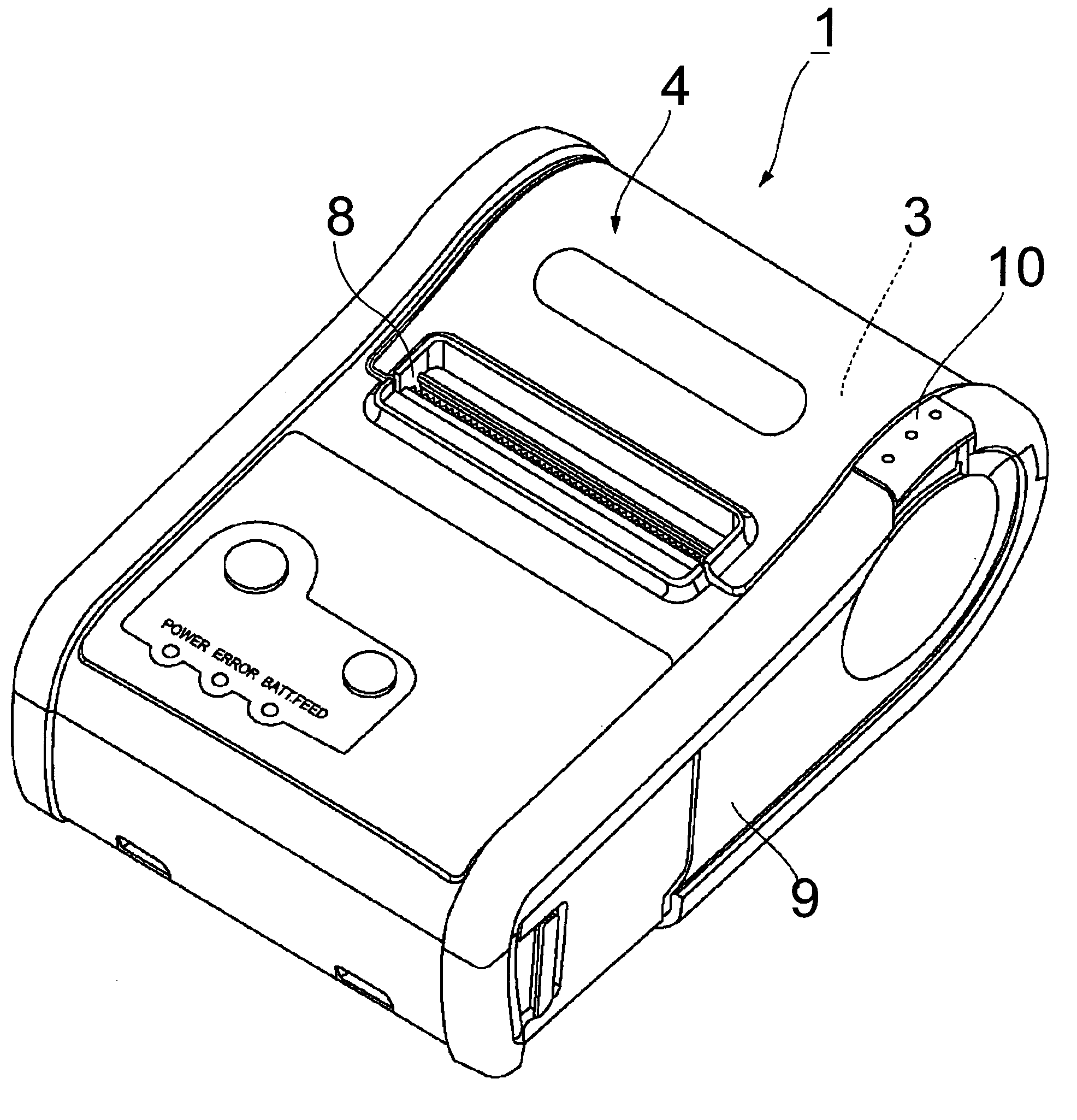
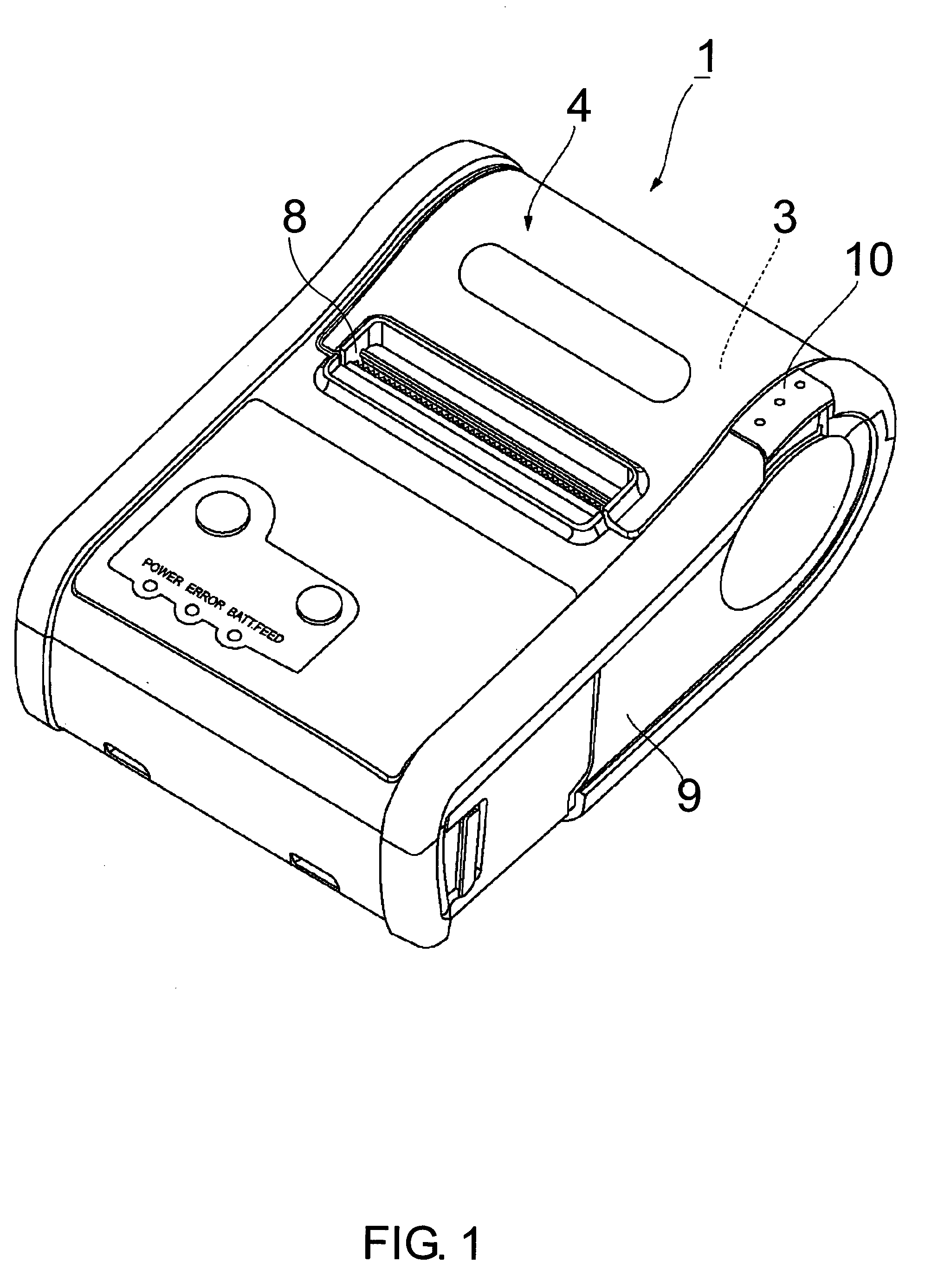
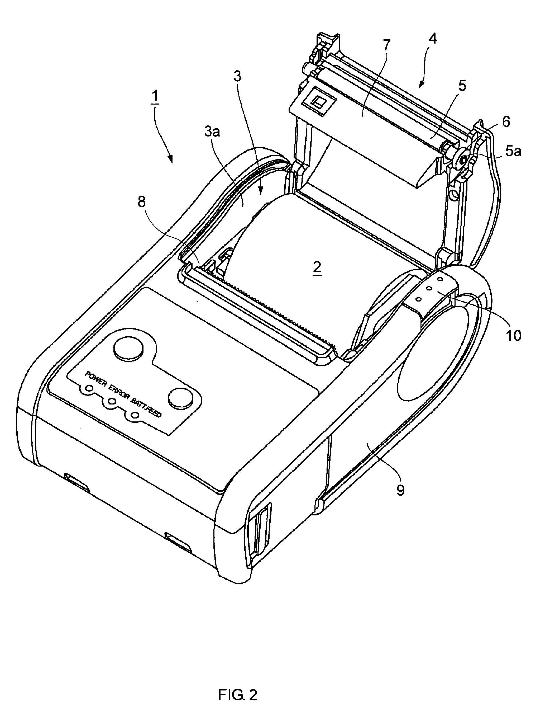
[0040]A printer 1 as is shown in FIGS. 1 through 4 respectively includes an outside case 9 representing the body of the printer 1 and a main chassis or frame 13 which is enclosed by the case 9. The printer 1 according to this embodiment of the invention is used, for example, as a portable receipt printer.

[0041]Inside the outside case 9 and at the back of the printer 1 is a compartment 3 for holding a paper roll 2. The paper roll 2 can be loaded or replaced through an opening 3a in the compartment 3. This opening 3a is normally closed by an operable cover 4 in the case 9 of the printer 1. More specifically, the operable cover 4 is pivotally hinged at the back of the printer 1 which permits rotation of the operable cover 4 between a closed position 4a as shown in FIG. 1 and a fully open position 4b as shown in FIG. 2.

[0042]A paper exit 8, in th...


PUM


Abstract

A locking / unlocking mechanism for an operable cover of a body such as a printer to lock and unlock the body with a single operation and to a printer having an operable cover and a locking / unlocking mechanism for the operable cover. The operable cover is locked when a cover side engaging part in the cover engages a body-side engaging part in the body. The printer has a cover opening button 10 which is depressed to a first operating position 10B, causing a locking lever 14 in the locking / unlocking mechanism 11 to slide from a locked position 14A to an unlocked position 14B. The locking lever has an engaging channel 15 which releases the cover-side engaging part 12 of the operable cover 4, thereby disengaging the operable cover 4 but not opening it. When the cover opening button 10 is further depressed to a second (final) operating position 10C, the locking lever 14 swings vertically pivoting on a guide pin 24, which causes a cover-lifting surface 16 of the locking lever 14 to push the cover-side engaging part 12 of the operable cover 4 upward which opens the operable cover 4. The operable cover 4 is thus both unlocked and opened by simply pressing the cover opening button 10.

Description

BACKGROUND OF THE INVENTION[0001]1. Field of Technology[0002]The present invention relates to a mechanism for locking and unlocking an operable cover in a body representing, for example, a machine such as a printer wherein the cover opens and closes a roll paper compartment and to a printer including a locking / unlocking mechanism for a cover. More specifically, the present invention relates to a locking / unlocking mechanism enabling an operable cover to be easily opened and closed with the cover unaffected by vibration and impact when in the closed position.[0003]2. Description of Related Art[0004]Printers having a compartment for holding roll paper or other continuous form paper inside the printer housing, and printing to the roll paper while pulling it from this compartment, are common. Such printers typically have the print head enclosed within the case of the printer, and a platen roller (paper feed roller) assembled in an operable cover with the platen roller disposed opposite t...

Claims


Application Information

Patent Timeline
Patent Type & Authority Patents(United States)
IPC IPC(8): B41J29/54B41J29/12B41J29/13B41J15/00
CPCB41J29/54Y10T292/1084Y10T292/0951Y10T292/1043Y10T292/0848A62B23/04A62B23/02Y10S55/33
Inventor YAMADA, MASAHIKOKAWAKAMI, HIDEKI
Owner SEIKO EPSON CORP
Learn More