
Wood-turning lathe

a technology of turning lathes and turning shafts, which is applied in the direction of turning machines, manufacturing tools, mechanical equipment, etc., can solve the problems of considerable increase in the size of the headstock, the adjustment range of the aforesaid speed ratio is relatively narrow, etc., and achieves the effect of increasing the torque of the drive shaft and increasing the torque ratio of the drive shaft to the rotor

Inactive Publication Date: 2005-07-12
LIAO HUI CHUAN
View PDF5 Cites 7 Cited by
  • Summary
  • Abstract
  • Description
  • Claims
  • Application Information

AI Technical Summary

Benefits of technology

[0007]Therefore, the object of this invention is to provide a wood-turning lathe which includes a torque converter for increasing the torque of a drive shaft.
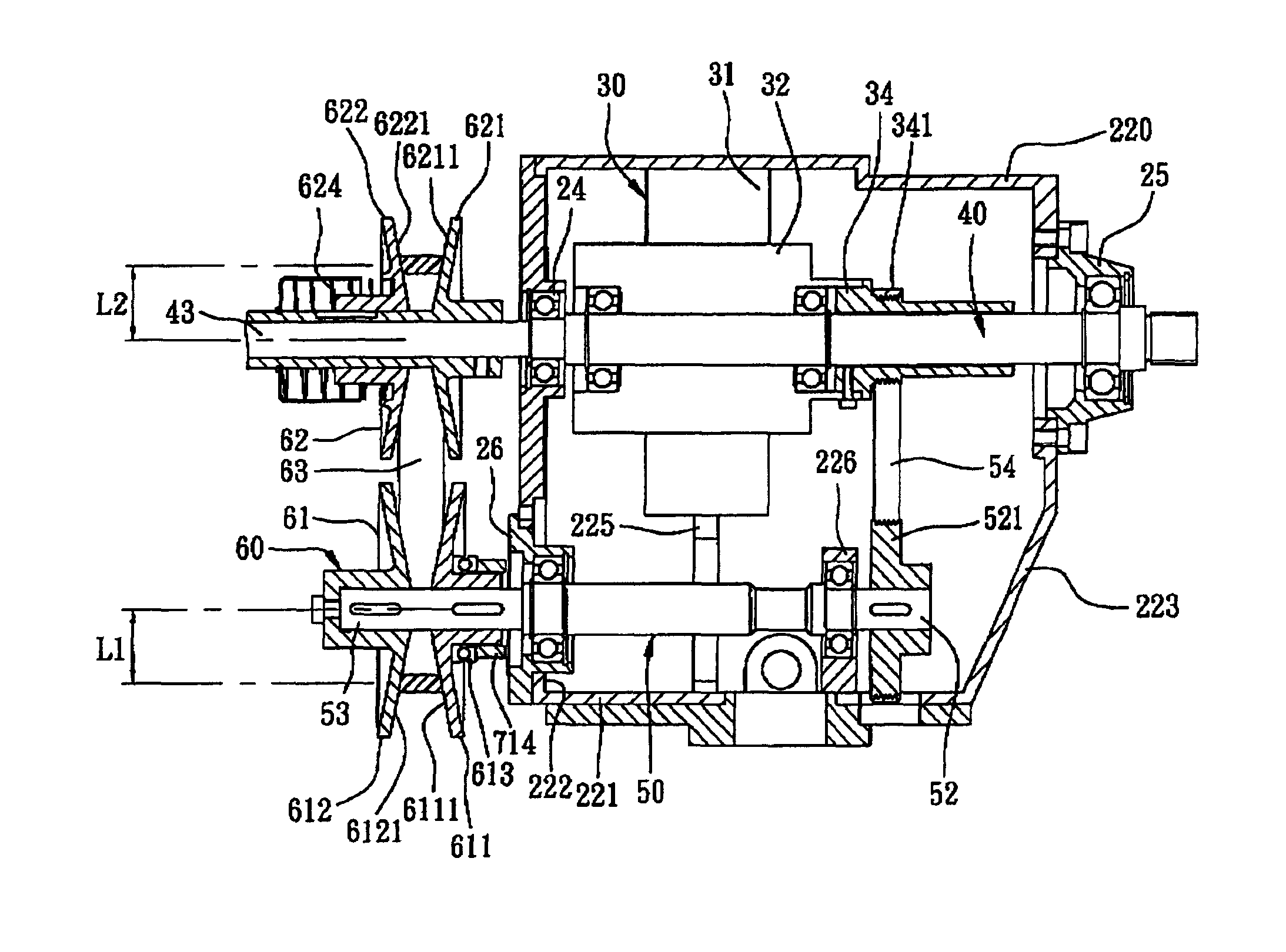
[0008]Accordingly, a wood-turning lathe of the present invention includes; a bed; a headstock housing mounted on the bed; a motor unit mounted in the headstock housing, and including a rotor; a spindle journalled to the headstock housing, extending co-axially through the rotor, and having an output end extending outwardly from the headstock housing; a drive shaft journalled to the headstock housing, parallel to the spindle, and having an outer coupling end that extends outwardly from the headstock housing and an inner coupling end that is opposite to the outer coupling end and that is disposed within the headstock housing; a torque converter including a first wheel that co-axially surrounds the spindle and that is securely and co-axially coupled to the rotor so as to co-rotate with the rotor, a second wheel mounted securely and co-axially on the inner coupling end of the drive shaft, and a transmission belt trained on the first and second wheels, the first wheel having a diameter less than that of the second wheel so that a torque ratio of the drive shaft to the rotor is greater than one; and a speed change device including a first pulley unit, a second pulley unit, and a non-elastic belt. The first pulley unit is mounted on the outer coupling end of the drive shaft, and includes a first fixed pulley and a first movable pulley which cooperatively define therebetween a radially and outwardly diverging first belt-engaging surface. The second pulley unit is mounted on the output end of the spindle, and includes a second fixed pulley and a second movable pulley which cooperatively define therebetween a radially and outwardly diverging second belt-engaging surface. The non-elastic belt is trained on and is in frictional contact with the first and second belt-engaging surfaces so as to permit power transmission from the drive shaft to the spindle.

Problems solved by technology

The conventional variable speed lathe is disadvantageous in that since the driving shaft is connected directly to the motor, the adjustable range of the aforesaid speed ratio is relatively narrow.
However, a larger space is required for accommodating a larger motor in the headstock, which results in a considerable increase in the size of the headstock.

Method used


Image

  • Wood-turning lathe
  • Wood-turning lathe
  • Wood-turning lathe

Examples


Embodiment Construction

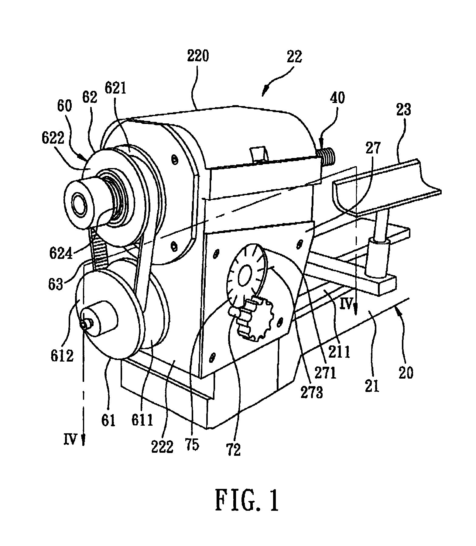
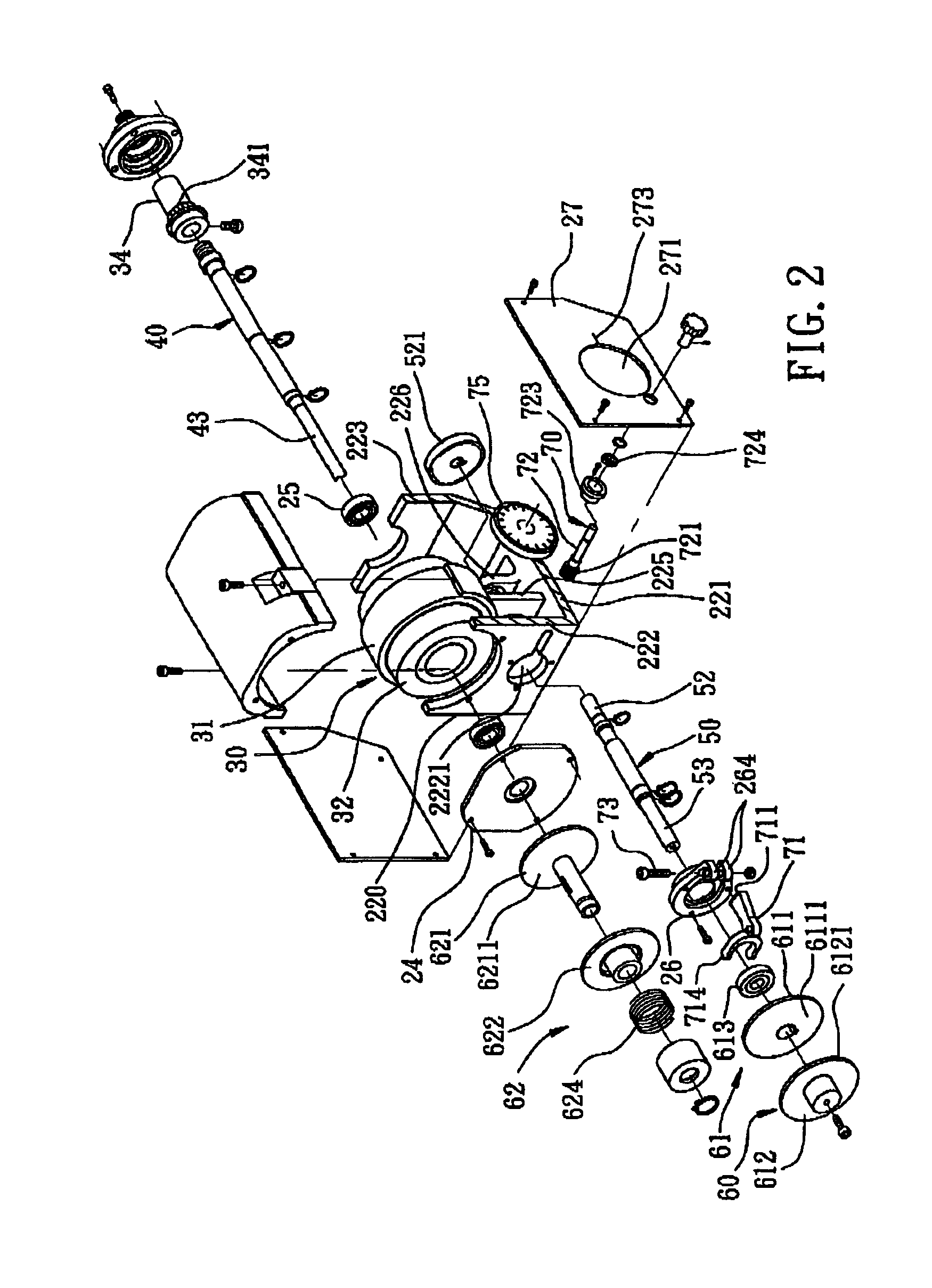
[0019]Referring to FIGS. 1 to 4, the preferred embodiment of a wood-turning lathe 20 according to the present invention is shown to include a lathe bed 21, a headstock 22 mounted on the bed 21, a tail-stock (not shown) mounted on the bed 21, a tool rest 23 mounted on the bed 21 between the headstock 22 and the tail-stock, a motor unit 30, a spindle 40, a drive shaft 50, a torque converter, and a speed change device 60.

[0020]As illustrated, the headstock 22 includes a headstock housing 220 that has a flat bottom 221 mounted on the upper surface 211 of the lathe bed 21, and opposite left and right side walls 222, 223 which extend upwardly from the flat bottom 221.

[0021]The spindle 40 is journalled between the side walls 222, 223 of the headstock housing 220 by means of two bearing units 24,25, and has an output end 43 that extends outwardly from the headstock housing 220.

[0022]The drive shaft 50 is journalled to the headstock housing 220 by means of two bearing units (613, 226), and i...


PUM

PropertyMeasurementUnit
diameteraaaaaaaaaa
torque ratioaaaaaaaaaa
torqueaaaaaaaaaa

Abstract

A wood-turning lathe includes a spindle and a drive shaft journalled to a headstock housing. A motor is mounted in the headstock housing, and includes a rotor. A torque converter includes a first wheel that co-axially surrounds the spindle and that is securely coupled to the rotor, a second wheel mounted securely on the drive shaft, and a belt trained on the first and second wheels, thereby increasing torque of the drive shaft. A speed change device includes a first pulley unit mounted on the drive shaft and defining a first belt-engaging surface, a second pulley unit mounted on the spindle and defining a second belt-engaging surface, and a non-elastic belt interconnecting the first and second pulley units and frictionally contacting the first and second belt-engaging surfaces.

Description

CROSS-REFERENCE TO RELATED APPLICATION[0001]This application is a Continuation-in-Part of U.S. patent application Ser. No. 09 / 882,350, filed on Jun. 15, 2001 abandoned, which claims priority of Taiwanese Patent Application No. 090207042, filed on May 1, 2001.BACKGROUND OF THE INVENTION[0002]1. Field of the Invention[0003]The invention relates to a wood-turning lathe, more particularly to a wood-turning latch with a torque converter for increasing the torque of a drive shaft.[0004]2. Description of the Related Art[0005]U.S. Pat. No. 5,186,088 discloses a variable speed lathe that includes a lathe bed and a headstock mounted on the lathe bed. The headstock includes a driving shaft driven by a motor, and a driven shaft connected to the driving shaft through a speed adjusting unit that includes speed variable driving and driven pulleys such that the speed ratio of the driven shaft to the driving shaft can be adjusted through the speed adjusting unit.[0006]The conventional variable speed...

Claims


Application Information

Patent Timeline
Patent Type & Authority Patents(United States)
IPC IPC(8): B23Q5/00B23Q5/16B27C7/00F16H61/662F16H61/66
CPCB23Q5/162B27C7/00F16H61/662Y10T82/2552Y10T82/2556Y10T82/2554Y10S82/905
Inventor LIAO, JUEI-SENG
Owner LIAO HUI CHUAN
Learn More