Radio base station for monitoring faults of radio communication modems based on content of received frames that are received during call connections

a radio communication modem and content technology, applied in the field of radio base stations, to achieve the effect of rapid recovery and rapid resolution of the reduction of the number of radio resources

Inactive Publication Date: 2005-07-05
NEC CORP
View PDF19 Cites 13 Cited by
  • Summary
  • Abstract
  • Description
  • Claims
  • Application Information

AI Technical Summary

Benefits of technology

[0010]It is an object of the present invention to provide a mobile communication system that performs a rapid recovery process when a fault occurs in a radio communication modem and that enables rapid resolution of the reduction of the number of radio resources, to provide a radio base station that is used in such a mobile communication system, and to provide fault recovery method of a radio communication modem of this radio base station.
[0011]In the radio communication modem fault recovery method of the present invention, the determination of whether or not a fault has occurred in each radio communication modem is realized on the side of the radio base station based on the content of the frames that are received by a plurality of radio communication modems that are mounted on a signal converter card for performing conversion of signals of radio sections and wired sections of a radio base station. When it is recognized that a fault has occurred in a radio communication modem after the termination of a call connection, the radio base station attempts the automatic recovery of the affected radio communication modem and quickly resolves the state in which the fault of the radio communication modem prevents call connection. In addition, when the number of detections of faults of a radio communication modem exceeds a particular threshold value, the radio base station prohibits use of that radio communication modem and does not assign resources for call origination or reception to that radio communication modem. Furthermore, when the total number of radio communication modems in which faults occur exceeds a particular threshold value in units of signal converter cards, maintenance personnel are prompted to exchange the card. In this way, rather than specifying a card in which failure has occurred based on the chief cause of call connection faults and the number of a radio communication modem that are indicated on a maintenance monitor device as in the prior art, the card that is to be exchanged is clearly indicated, whereby the reduction of the number of resources of radio communication modems can be quickly and easily resolved.

Problems solved by technology

In addition, when the number of detections of faults of a radio communication modem exceeds a particular threshold value, the radio base station prohibits use of that radio communication modem and does not assign resources for call origination or reception to that radio communication modem.

Method used


Image

  • Radio base station for monitoring faults of radio communication modems based on content of received frames that are received during call connections
  • Radio base station for monitoring faults of radio communication modems based on content of received frames that are received during call connections
  • Radio base station for monitoring faults of radio communication modems based on content of received frames that are received during call connections

Examples


Embodiment Construction

[0023]We next refer to the accompanying drawings to describe the details of an embodiment of the present invention.

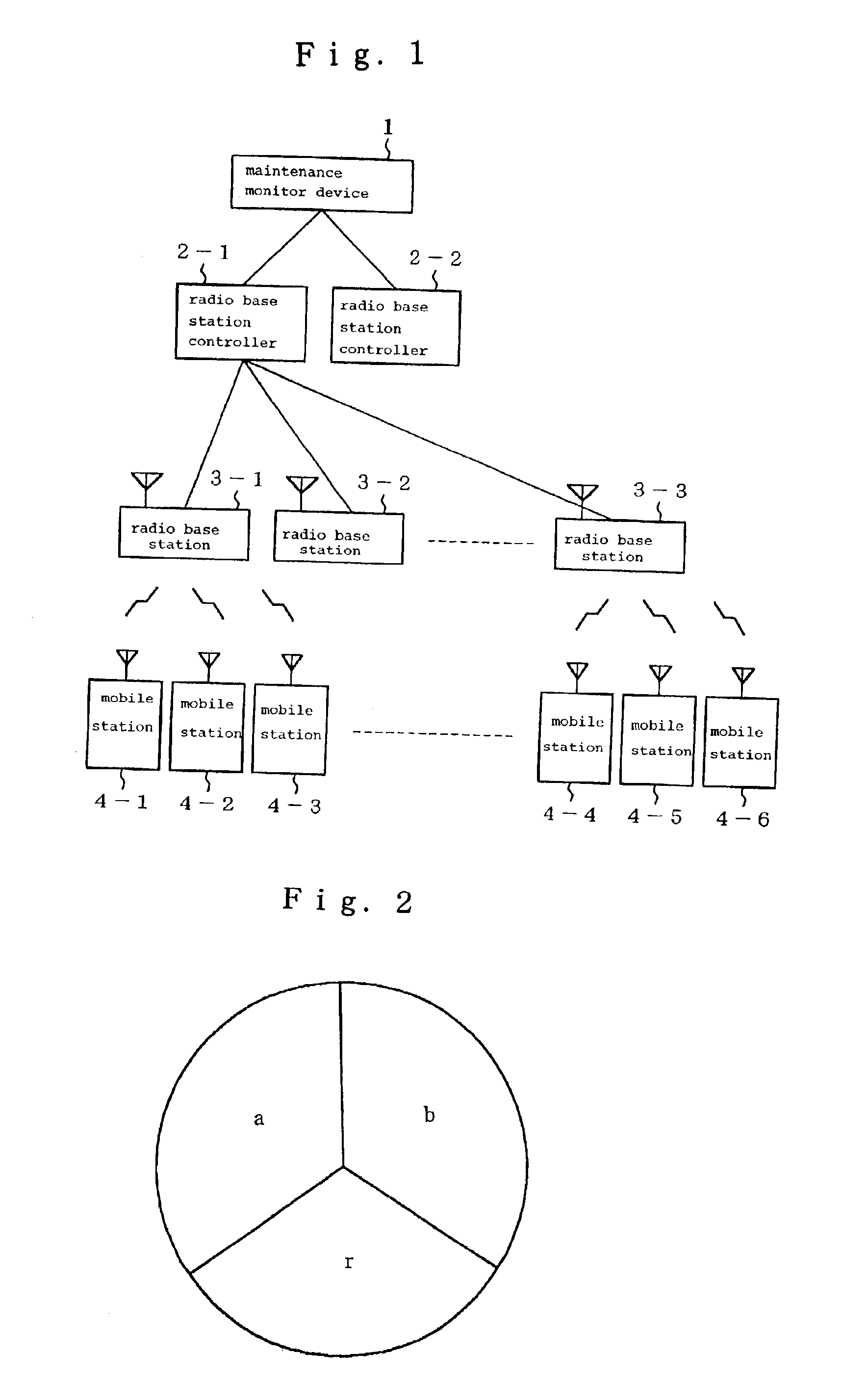
[0024]FIG. 1 is a system structure diagram showing an embodiment of the mobile communication system of the present invention. A plurality (two in the figure) of radio base station controllers 2 (2-1 and 2-2) are connected by way of a wired network to a single maintenance monitor device 1 that is managed by the maintenance personnel of a system. A plurality (three in the figure) of radio base stations 3 (3-1, 3-2, and 3-3) are connected by way of a wired network to each radio base station controller 2. Each of a plurality (six in the figure) of mobile stations 4 (4-1, 4-2, 4-3, 4-4, 4-5, and 4-6), which are user terminals, can freely exist in the wireless service areas of each radio base station 3. Each radio base station controller 2 is accommodated in a core network (not shown in the figure) and acts as an intermediary for communication between each mobile station 4 an...


PUM


Abstract

A radio base station is disclosed that monitors faults of radio communication modems based on the content of received frames that are received during call connection. The radio communication modems are mounted in units of prescribed number on signal converters of card structure and are assigned to correspond to mobile stations that perform call connections. The radio base station uses fault detection data to check the content of frames that are received during call connections for each radio communication modem, and counts the total number of received frames and the number of frames in which faults are detected. Upon termination of a call connection, the radio base station determines whether or not a fault has occurred in a radio communication modem based on the counted ratio of the number of frames in which faults are detected to the total number of received frames, and if a fault has occurred, attempts recovery control. If a radio communication modem does not recover, the radio base station deletes the radio communication modem as a candidate for next assignment. The radio base station further transmits, to maintenance personnel through the radio base station controller, a message prompting exchange of a signal conversion card in which the number of faulty radio communication modems reaches or exceeds a particular number.

Description

BACKGROUND OF THE INVENTION[0001]1. Field of the Invention[0002]The present invention relates to a radio base station in which radio communication modems are mounted for communicating with mobile stations in a mobile communication system, to a fault recovery method for the radio communication modems, and to a mobile communication system that employs this radio base station and fault recovery method.[0003]2. Description of the Related Art[0004]We first refer to FIGS. 1 and 2 to explain the construction of a typical mobile communication system, for example, a mobile communication system that adopts a CDMA (Code Division Multiple Access) communication method.[0005]Referring to FIG. 1, the mobile communication system is configured such that a plurality of radio base station controllers 2-1 and 2-2 are connected to one maintenance monitor device 1, a plurality of radio base stations 3 (3-1, 3-2, and 3-3) are connected to one radio base station controller 2-1, and a plurality of mobile st...

Claims


Application Information

Patent Timeline
Patent Type & Authority Patents(United States)
IPC IPC(8): H04Q7/34H04M3/12H04B7/26H04M3/22H04M3/24H04W24/00
CPCH04W24/00
Inventor SAKUMA, MASAKI
Owner NEC CORP
Why Eureka
Try Eureka