
Switching power supply apparatus with blanking pulse generator

a technology of power supply apparatus and pulse generator, which is applied in the direction of electric variable regulation, process and machine control, instruments, etc., can solve the problems of insufficient blanking interval, and inability to meet the requirements of the power supply

Inactive Publication Date: 2005-07-05
PANASONIC CORP
View PDF9 Cites 76 Cited by
  • Summary
  • Abstract
  • Description
  • Claims
  • Application Information

AI Technical Summary

Benefits of technology

[0062]An object of the present invention is to provide a switching power supply apparatus in which the blanking interval can be changed in accordance with load conditions such as those existing during no load, a light load, or a heavy load, and that is capable of normal element current control for an entire range of loads.
[0073]a mirror circuit that is connected to a constant current source and is capable of varying the outflow rate of the current from the blanking interval generating capacitor in two steps,

Problems solved by technology

However, in the switching power supply apparatus, the blanking interval is fixed, so there is a possibility that the drawbacks described below may occur.
However, during no load or a light load, a blanking interval tBLK that has been set for times of heavy loads may be too long, and there is possibility that an element current will flow that is equal to or greater than the current value that should flow to the switching element.
This results in a drawback whereby more energy than is required is transmitted to the secondary side (output side) of the transformer, and the output voltage Vo becomes equal to or exceeds the prescribed voltage.
As a result, a drawback occurs whereby the element current ID (b) flows only for a very short interval, the required energy with respect to the load is not transmitted to the secondary side of the transformer, and the output voltage Vo becomes equal to or less than the prescribed voltage.
As a result, when an interval is set that is sufficient to prevent malfunction due to capacitive spike current even during a heavy load, the element current is controlled by the minimum pulse interval during no load or a light load, maximum energy is transmitted to the secondary side, and the output voltage increases excessively.
Conversely, when the blanking interval tBLK is set in accordance with no load or a light load, then a malfunction occurs whereby the switching element is turned off by the capacitive spike current during a heavy load, the interval in which the element current flows is short, the energy required for the load is not transmitted to the secondary side, and the prescribed output voltage cannot be obtained.
Nevertheless, adding a dummy resistance is disadvantageous in that the power supply efficiency is reduced or the like.

Method used


Image

  • Switching power supply apparatus with blanking pulse generator
  • Switching power supply apparatus with blanking pulse generator
  • Switching power supply apparatus with blanking pulse generator

Examples


Embodiment Construction

[0105]An embodiment of the present invention is described below with reference to the diagrams. The embodiment described herein is no more than an example, and the present invention is not limited to this embodiment.

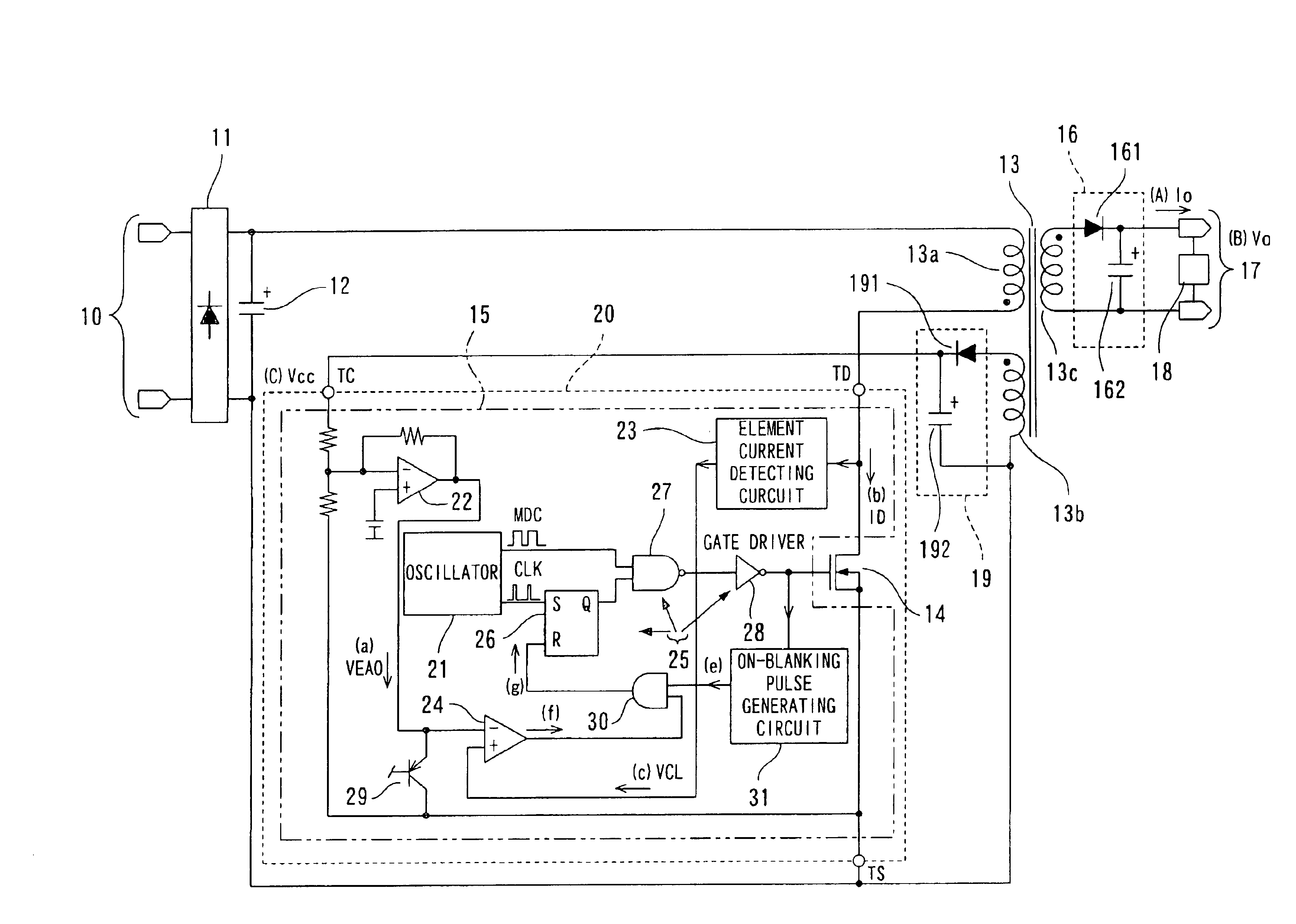
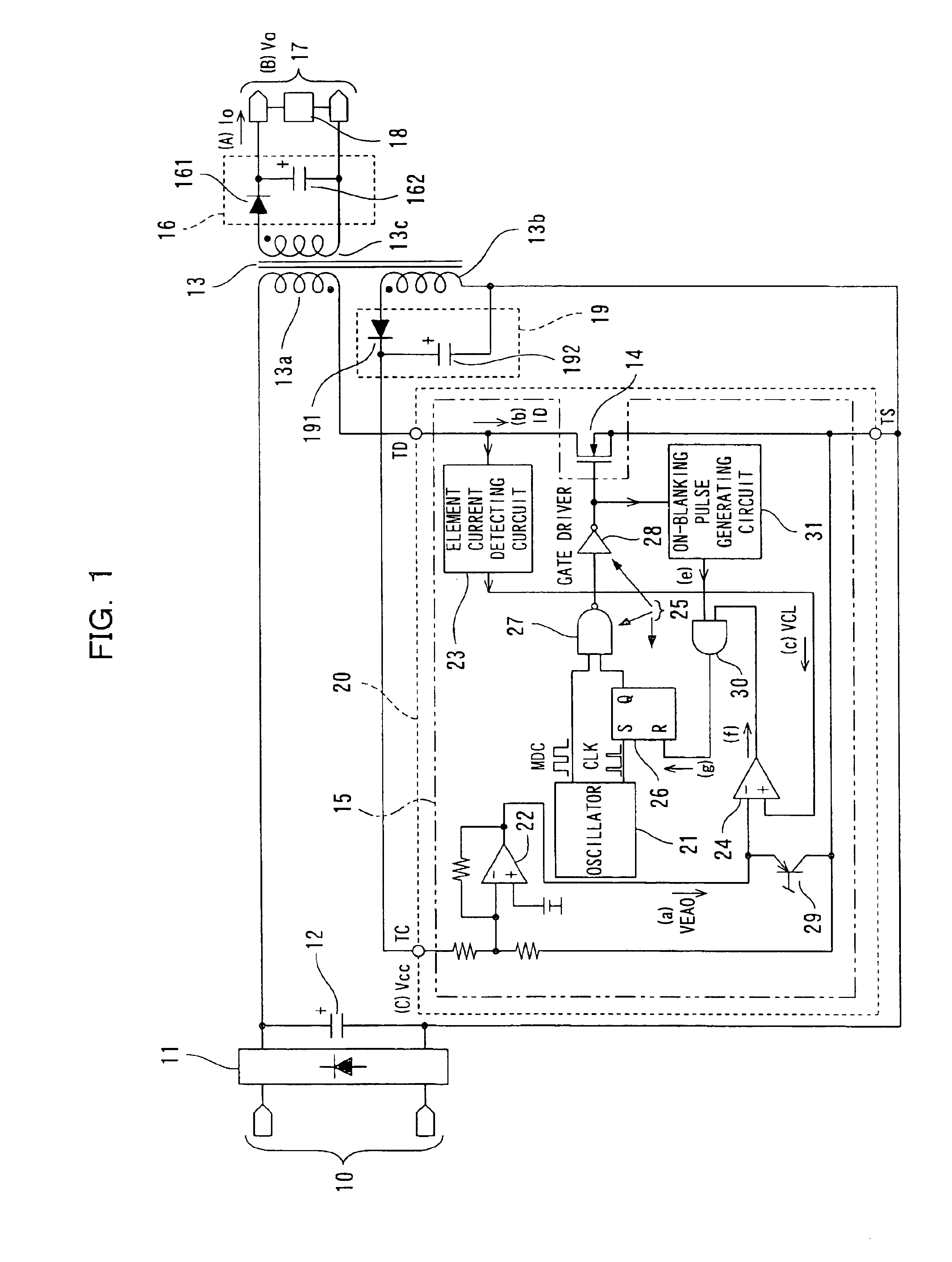
[0106]FIG. 1 is a circuit diagram showing an outline of an insulated-type switching power supply apparatus, in which the input and output sides are insulated, related to an embodiment of the present invention.

[0107]As shown in FIG. 1, the switching power supply apparatus rectifies and smoothes the AC electric power that is applied to a main input terminal 10 from, for example, a commercial power supply or the like, and forms DC voltage Vin, which is a first DC voltage. The switching power supply apparatus performs switching action by means of a switching element 14 while applying this DC voltage Vin to the winding on the primary side (first primary winding 13a; hereinafter simply referred to as primary winding 13a) of the a transformer (converter) 13 for converting elect...


PUM


Abstract

A switching power supply apparatus is provided, wherein an optimal blanking interval can be obtained for an entire load range. The switching power supply apparatus is configured such that an on-blanking pulse signal generating circuit 31 generates a blanking pulse signal based on an error voltage signal VEAO, and sets a blanking interval that corresponds to the load condition. For example, the reference voltage and the voltage value of the error voltage signal VEAO are compared and the blanking pulse signal that shortens the blanking interval is generated during a light load, that is, when the voltage value of the error voltage signal VEAO is less than or equal to the reference voltage.

Description

BACKGROUND OF THE INVENTION[0001]1. Field of the Invention[0002]The present invention relates to a switching power supply apparatus.[0003]2. Related Art[0004]A conventional switching power supply is described below with reference to the diagrams. FIG. 8 is a circuit diagram showing an outline of a conventional insulating-type switching power supply apparatus in which the input side and the output side are electrically insulated.[0005]The switching power supply apparatus is configured such that AC electric power applied to a main input terminal 101 from a commercial power supply or the like, for example, is rectified by a rectifier 102 comprising a diode bridge or the like, smoothed by an input capacitor 103, and applied as DC voltage Vin to a first primary winding 104a of a transformer 104 for electric power conversion, as shown in FIG. 8. This primary winding 104a is connected to a switching element 105 comprising an N-type power MOSFET or the like, for example, and the switching p...

Claims


Application Information

Patent Timeline
Patent Type & Authority Patents(United States)
IPC IPC(8): H02M3/28H02M3/335H02M3/24
CPCH02M3/33507H02M2001/0032Y02B70/16Y02B70/10H02M1/0032
Inventor KINOSHITA, TOMOKOMORI, YOSHIHIRO
Owner PANASONIC CORP
Learn More