
Method and apparatus for preventing ESD and EOS damage in manufacturing magnetoresistive effect read heads

a technology of magnetoresistive effect and manufacturing method, which is applied in the field of magnetoresistive head manufacture, can solve the problems of eos mr reader damage, mr head temperature adversely affecting the lifetime of mr head, and increased susceptibility to esd or eos, and achieves high and low resistance states

Inactive Publication Date: 2005-07-05
SEAGATE TECH LLC
View PDF16 Cites 17 Cited by
  • Summary
  • Abstract
  • Description
  • Claims
  • Application Information

AI Technical Summary

Benefits of technology

[0010]In some embodiments, the second reader includes a phase change thin ...

Problems solved by technology

The increase in the temperature in the MR head adversely affects the lifetime of the MR head.
When an MR reader or sensor is exposed to an ESD, or even a voltage or a current input larger than that intended under normal operating conditions, referred to as EOS the MR reader may be damaged.
As MR readers are made smaller and more sensitive, their susceptibility to ESD or EOS has increased and the voltage at which damage may occur has continued to fall.
However, this approach has significant disadvantages.
In diode or MOSFET approaches, the turn-on voltage is difficult to control, and may not be small enough to protect the MR element.
However, this technique presents challenges and provides disadvantages as well.
First, fabrication of a parallel resistor can, in many instances, add additional process steps to the steps required to fabricate the MR reader.
Also, the addition of a parallel protective resistor can make it difficult to test the MR reader during the fabrication process.
Further, a parallel resistor provides little information to aid in the fabrication process.
For example, since a parallel resistor does not react in the same manner to external stimulus, such as the presence of a magnetic field, inclusion of such a resistor renders it more difficult to analyze the response of the MR reader to the stimulus during manufacturing.
While shorting out the MR sensor element provides very good ESD or EOS protection, it also removes the possibility of testing the MR reader after the short is applied.

Method used


Image

  • Method and apparatus for preventing ESD and EOS damage in manufacturing magnetoresistive effect read heads
  • Method and apparatus for preventing ESD and EOS damage in manufacturing magnetoresistive effect read heads
  • Method and apparatus for preventing ESD and EOS damage in manufacturing magnetoresistive effect read heads

Examples


Embodiment Construction

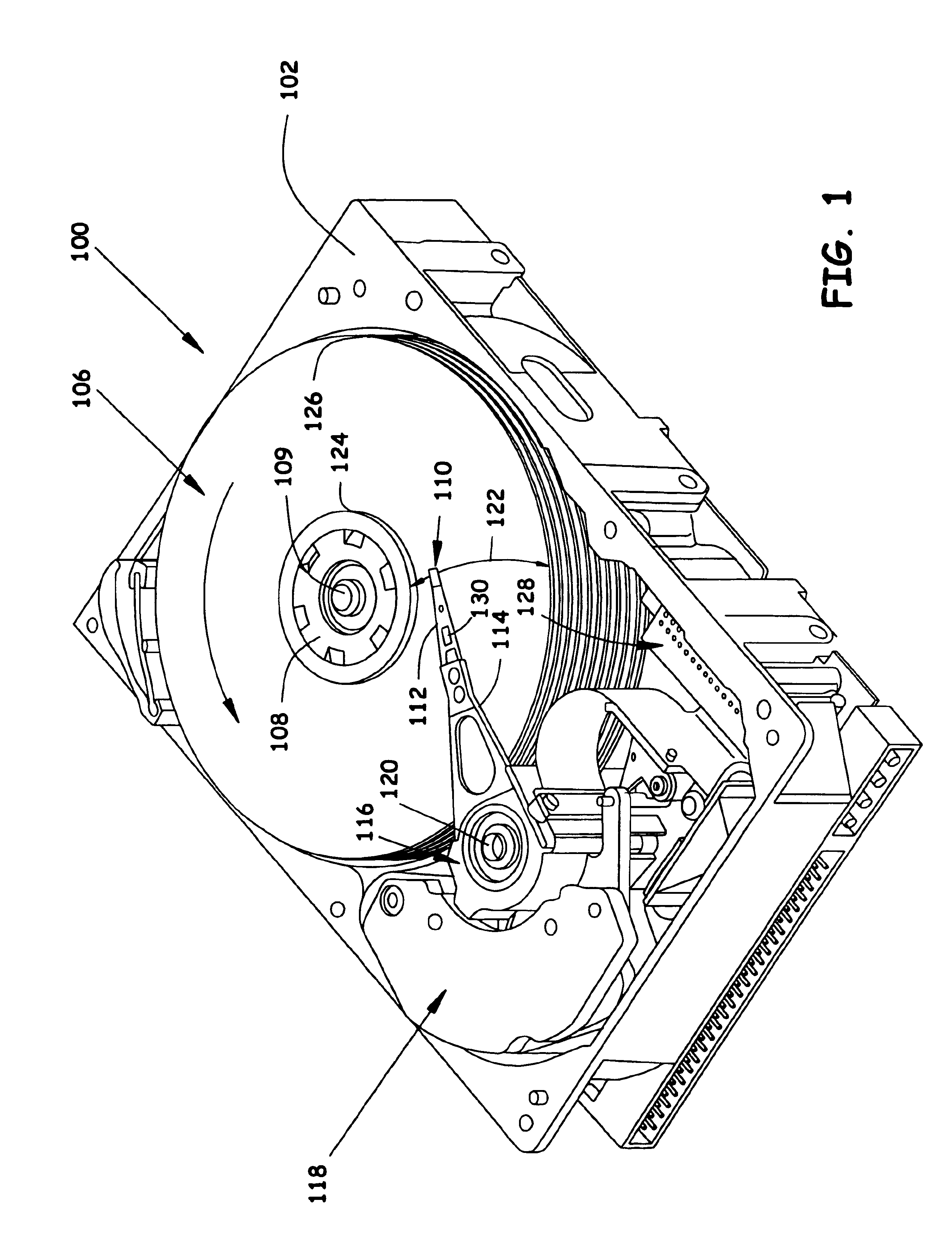
[0022]Referring to FIG. 1, a perspective view of a disc drive 100 is shown. The present invention is useful in fabricating MR readers of the MR heads in disc drive 100. Disc drive 100 includes a housing with a base 102 and a top cover (not shown). Disc drive 100 further includes a disc pack 106, which is mounted on a spindle motor (not shown), by a disc clamp 108. Disc pack 106 includes a plurality of individual discs, which are mounted for co-rotation about central axis 109.

[0023]Each disc surface has an associated disc head slider 110 which is mounted to disc drive 100 for communication with the disc surface. Sliders 110 support MR heads for reading data from the disc surface. The MR heads include MR readers or sensors, or in the alternative, the MR heads can be considered to be the MR readers. In the example shown in FIG. 1, sliders 110 are supported by suspensions 112 which are in turn attached to track accessing arms 114 of an actuator 116. The actuator shown in FIG. 1 is of th...


PUM


Abstract

A magnetoresistive head apparatus includes first and second readers. The first reader is a magnetoresistive reader. The second reader provides electrostatic discharge protection for the first magnetoresistive reader. The second reader can be a second magnetoresistive reader having substantially the same film structure as the first reader. The second reader can also include a phase change thin film, which has high and low resistance states that are changeable using a laser.

Description

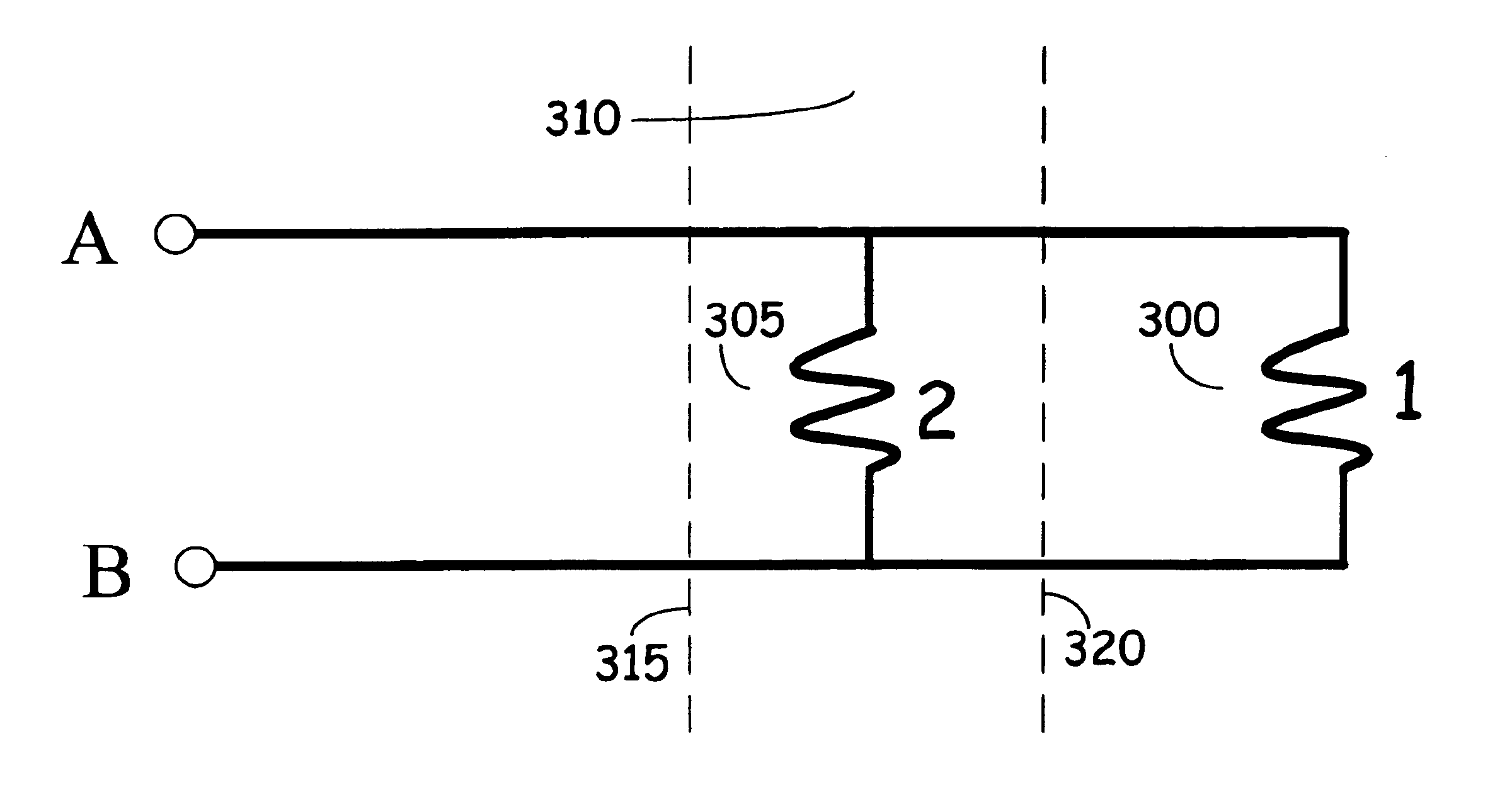
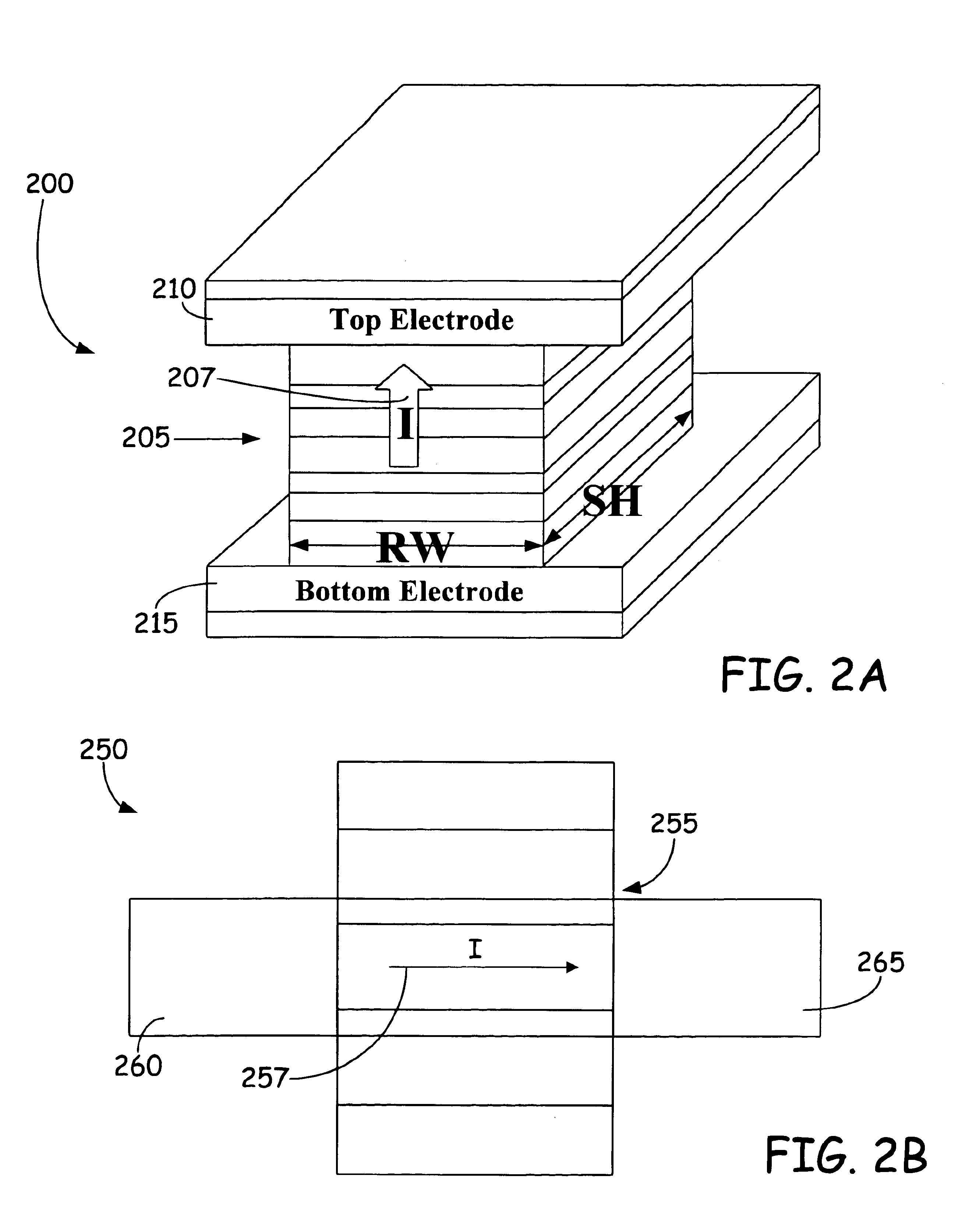
CROSS-REFERENCE TO RELATED APPLICATION[0001]This application claims priority from U.S. Provisional Application No. 60 / 419,989 filed on Oct. 21, 2002 for inventors Patrick Joseph Ryan and Song Sheng Xue and entitled NOVEL METHODS TO PREVENT ESD AND EOS DAMAGE IN MANUFACTURING CPP TYPE MAGNETO-RESISTIVE EFFECT READ HEADS.FIELD OF THE INVENTION[0002]The present invention relates generally to the manufacture of magnetoresistive (MR) heads, and more particularly but not by limitation to methods and apparatus for preventing electrostatic discharge (ESD) and electrical overstress (EOS) damage during the manufacture of MR heads.BACKGROUND OF THE INVENTION[0003]Various applications utilize MR heads to sense the presence of a magnetic field. For example, many current hard disc drive data storage systems use heads employing high sensitivity giant magnetoresistive (GMR) readers to read the data from the recording media. Future generation MR heads are expected to use current perpendicular-to-pla...

Claims


Application Information

Patent Timeline
IPC IPC(8): G11B5/39G11B5/31G11B5/40G11B5/49
CPCB82Y10/00B82Y25/00G11B5/3166G11B5/3173G11B5/3189G11B5/3903G11B5/3909G11B5/40G11B5/3103G11B5/3133G11B5/4984G11B2005/3996
Inventor RYAN, PATRICK JOSEPHXUE, SONG SHENG
Owner SEAGATE TECH LLC
Learn More