
Actuating device

a technology of actuating device and actuator, which is applied in the direction of valve operating means/releasing devices, machines/engines, mechanical apparatus, etc., can solve the problems of increasing energy expenditure and need, and achieve the effect of simple and cost-effective construction and energy saving

Active Publication Date: 2005-07-05
CONTINENTAL AUTOMOTIVE GMBH
View PDF4 Cites 15 Cited by
  • Summary
  • Abstract
  • Description
  • Claims
  • Application Information

AI Technical Summary

Benefits of technology

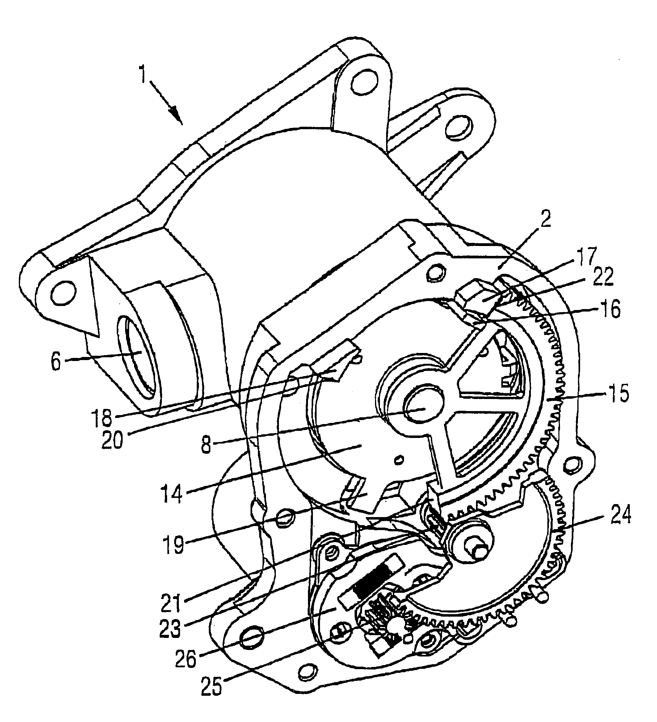
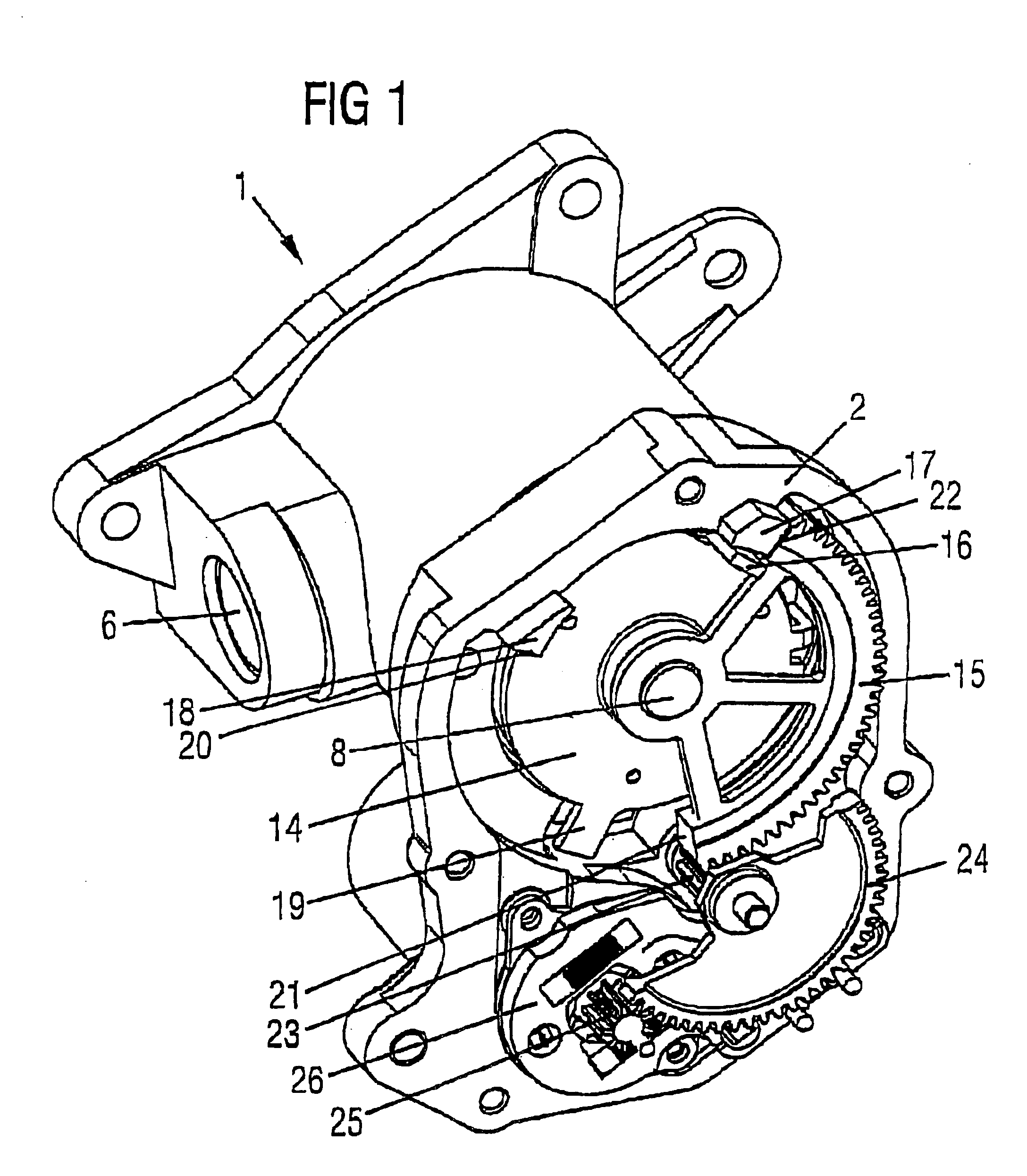
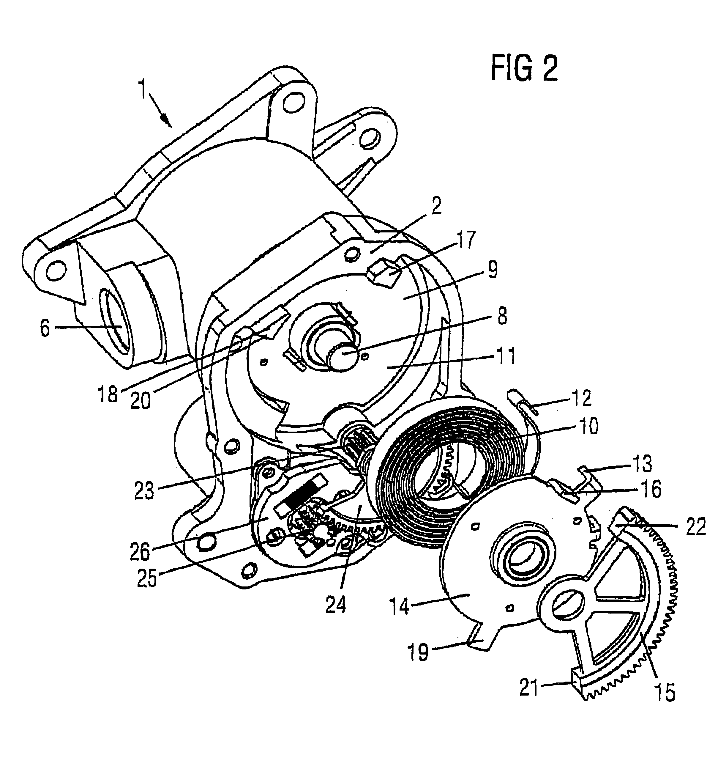
[0006]An object of the present invention is to provide an actuating device of the type initially mentioned above, which, in the event of a failure of its electromotive rotary drive, ensures that an intermediate position of the actuating element is assumed. The instant drive would operate with a saving of energy and further have a simple and cost-effective construction.

Problems solved by technology

Spring action upon the actuating element is effective between the first end position and an intermediate position and is ineffective between the intermediate position and the second end position.
Since the actuating element is adjusted and held counter to the force of the spring between the first end position and the middle position only, an increased expenditure of energy is necessary only in this actuating range.

Method used


Image

  • Actuating device
  • Actuating device
  • Actuating device

Examples


Embodiment Construction

[0036]The present invention will be described with respect to a rotary slide valve as being a regulating valve for an internal combustion engine coolant system. The present actuating device drives the rotary slide. For clarity purposes, details about the coolant system and internal combustion engine are not depicted. It is within the scope of the present invention that it find application beyond that discussed below.

[0037]As depicted in FIG. 3, the present regulating valve comprises a rotary slide 3 rotatably mounted in a rotary-slide chamber 1 of an actuating-device housing 2. The regulating valve includes two radial flow passages 4 and 5. The rotary chamber includes a short-circuit outlet 6 and a cooling outlet 7. The flow passages 4 and 5 are positioned on the rotary slide such that the slide 3, in a first position 40, shuts or seals off the rotary chamber to both outlets 6 and 7, and in a second position 50, the short-circuit outlet remains open, while the cooling outlet remains...


PUM


Abstract

The present invention relates to an actuating device with an electromotive rotary drive, via which an actuating element can be driven rotatably about an axis of rotation between a first end position and a second end position and can be acted upon out of the first end position by a spring. The electromotive actuating drive includes a reversing drive and the spring action upon the actuating element is effective between the first end position and an intermediate position. The spring action is ineffective between the intermediate position and the second end position. The intermediate position lies between the first end position and the second end position.

Description

CROSS-REFERENCE TO RELATED APPLICATIONS[0001]The present application claims priority to German patent application number 10243778.5 filed on 20 Sep. 2002, which is herein incorporated by reference.BACKGROUND OF THE INVENTION[0002]The present invention relates to an actuating device with an electromotive rotary drive and more particularly to the actuating element, which can be driven rotatably about an axis of rotation between a first end position and a second end position and further acted upon out of the first end position by a spring.[0003]In actuating devices of this type, it is known to operate the actuating element by means of the electromotive rotary drive counter to the force of the spring and over the entire actuating travel between the first and second end positions. During operation of the actuating device, a permanent operation of the electromotive actuating drive is also required. A permanent supply of current and therefore a permanent expenditure of energy is also conse...

Claims


Application Information

Patent Timeline
IPC IPC(8): F01P7/16F01P7/14H02K7/116
CPCF01P7/167H02K7/116F01P2007/146F01P2031/32F01P2031/34
Inventor BERNARDING, EUGENCOLIC, RAJKOMANN, THOMAS
Owner CONTINENTAL AUTOMOTIVE GMBH
Learn More