Shock-absorbing mechanism for power-transmission device
a technology of shock-absorbing mechanism and power-transmission device, which is applied in the direction of shock-absorbing devices, elastic dampers, couplings, etc., can solve the problems of insufficient collision energy absorption, inability to fully respond to the required shock-absorbing load of the vehicle, and inability to absorb collision energy. , to achieve the effect of high rigidity, considerable strength and great energy
- Summary
- Abstract
- Description
- Claims
- Application Information
AI Technical Summary
Benefits of technology
Problems solved by technology
Method used
Image

Examples
second embodiment
[0045]Referring to FIG. 6, there is shown second embodiment of the present invention wherein C-ring 17 is arranged inside sealing plate 15, and not outside it, so that with a stroke of driving-side shaft 2, balls 13 of constant-velocity joint 4 overpass C-ring 17 directly. Thus, a friction resistance is slightly greater than that when overpassing sealing plate 15, obtaining increased energy absorbing ability.
[0046]Referring to FIG. 7, there is shown third embodiment of the present invention wherein an outside face 15a of the outer periphery of sealing plate 15 on the C-ring 17 side is tapered. Thus, with a stroke of driving-side shaft 2, sealing plate 15 can overpass C-ring 17 easily, having smaller friction resistance, resulting in excellent stroke-ability of driving-side shaft 2. Therefore, the third embodiment is preferably applicable to a shock-absorbing mechanism requiring not so great friction resistance resulting from sealing plate 15.
fourth embodiment
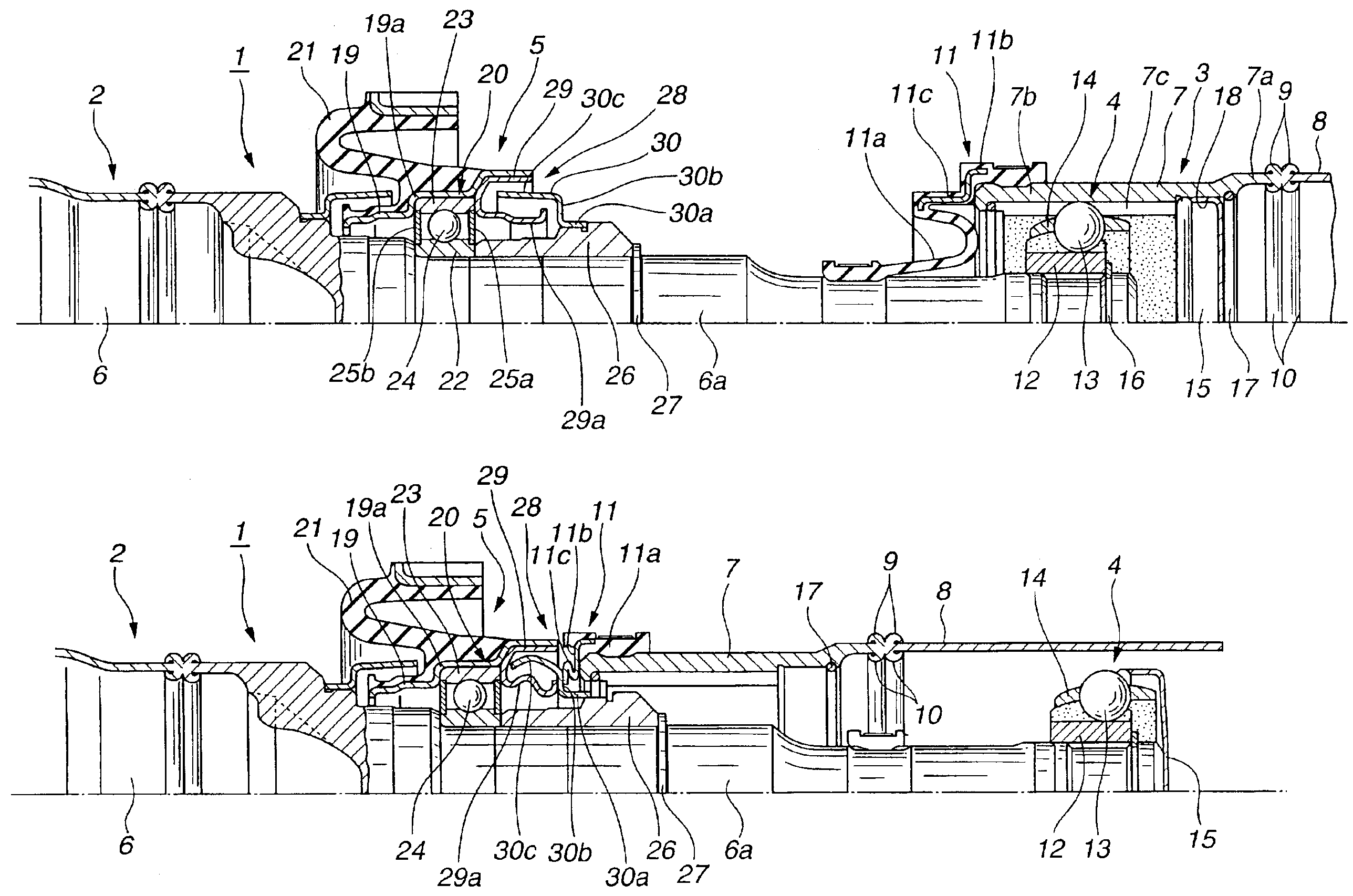
[0047]Referring to FIGS. 8-10, there is shown fourth embodiment of the present invention wherein the outer diameter of holder 7 of driven-side shaft 3 and that of tubular shank 8 are set equal to each other, the position of friction welding between the two 7, 8 is set adjacent to sealing plate 15, and the inner diameter of inside curl 10 produced by friction welding is set smaller than the outer diameter of sealing plate 15. Boot 11 comprises rubber main body 11a and reinforcing core 11b formed separately.
[0048]In the fourth embodiment, therefore, as shown in FIG. 10, with a stroke of driving-side shaft 2, an end of cage 14 of constant-velocity joint 4 meets the inside face of the outer periphery of sealing plate 15 to push sealing plate 15 inward of tubular shank 8. Then, the outer periphery of sealing plate 15 meets and overpasses the side of inside curl 10 in being deformed, producing a relatively great friction resistance. Thus, an 10 effective absorption of collision energy can...
PUM
 Abstract
Description
Claims
Application Information
 - R&D
- Intellectual Property
- Life Sciences
- Materials
- Tech Scout
- Unparalleled Data Quality
- Higher Quality Content
- 60% Fewer Hallucinations
Browse by: Latest US Patents, China's latest patents, Technical Efficacy Thesaurus, Application Domain, Technology Topic, Popular Technical Reports.
© 2025 PatSnap. All rights reserved.Legal|Privacy policy|Modern Slavery Act Transparency Statement|Sitemap|About US| Contact US: help@patsnap.com