
Engine control to reduce impacts due to transmission gear lash while maintaining high responsiveness to the driver

a technology of transmission gear lash and engine control, which is applied in the direction of electric control, control devices, vehicle components, etc., can solve the problems of poor driveability, poor driveability and customer dissatisfaction, and the disadvantage of the prior art is exacerbated, so as to improve refinement and response, the effect of improving the drive feel

Inactive Publication Date: 2005-06-28
FORD GLOBAL TECH LLC
View PDF14 Cites 31 Cited by
  • Summary
  • Abstract
  • Description
  • Claims
  • Application Information

AI Technical Summary

Benefits of technology

[0010]An advantage of the present invention is that it is possible to improve drive feel, while at the same time still providing responsive engine output to driver requests. As such, improved refinement and response are simultaneously achieved, even when the driver is applying the accelerator pedal under various vehicle operating conditions.

Problems solved by technology

It is known that there is the potential for poor driveability when the vehicle operator releases and subsequently engages the accelerator pedal.
Specifically, as described in U.S. Pat. No. 6,266,597, this results due to transmission or driveline gear lash.
This series of events produces an impact, or clunk, resulting in poor driveability and customer dissatisfaction.
This disadvantage of the prior art is exacerbated when the operator returns the accelerator pedal to a depressed position, indicating a desire for increased engine torque.
However, in this situation, the engine is producing a larger amount of torque than during deceleration because the driver is requesting acceleration.
Thus, another, more severe, impact is generally experienced due to the transmission or driveline lash during the zero torque transition.
However, the inventors herein have recognized a disadvantage with such an approach.
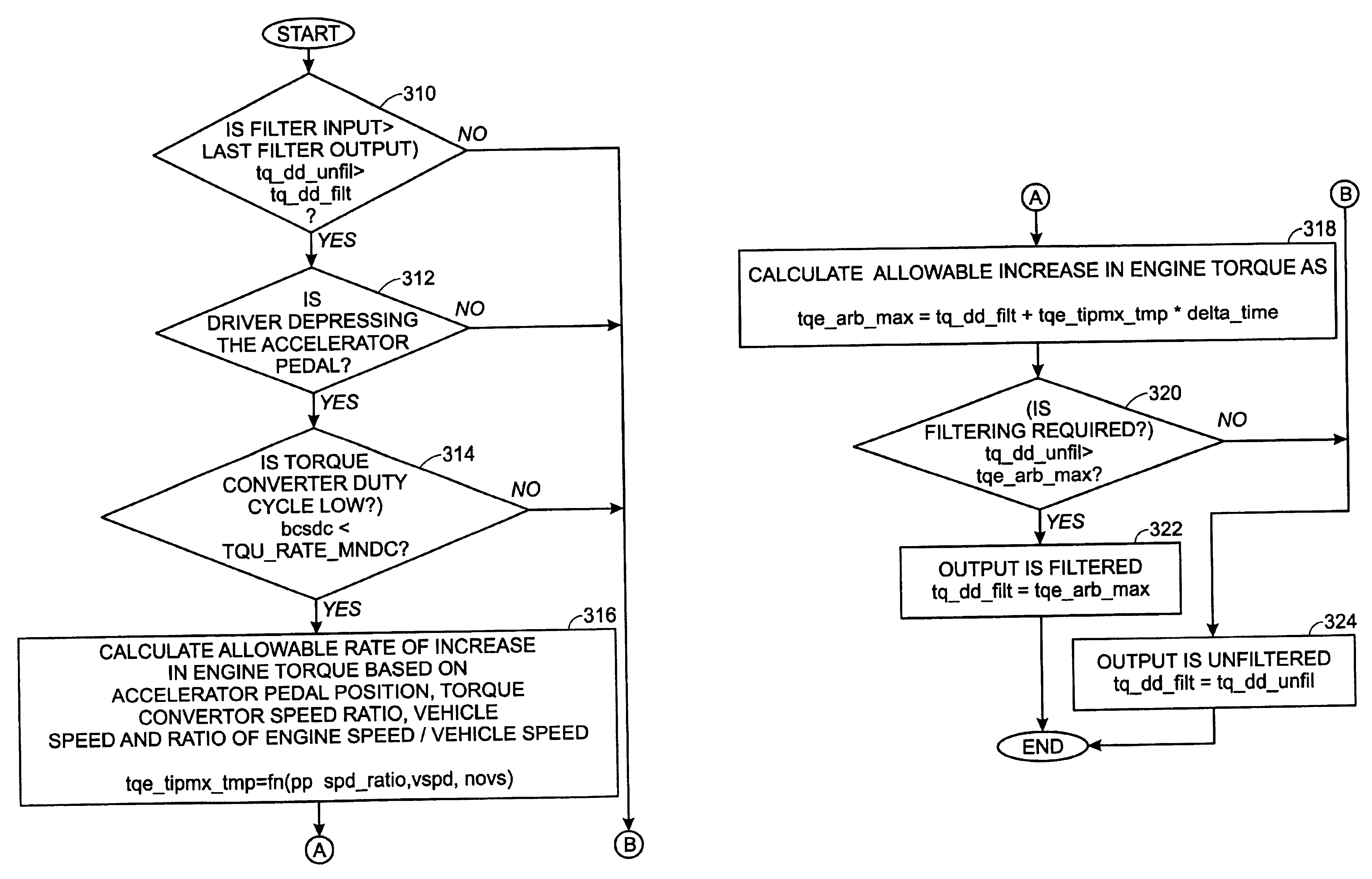
In particular, not all situations require rate limiting, and in particular, some situations require more or less filtering than others.

Method used


Image

  • Engine control to reduce impacts due to transmission gear lash while maintaining high responsiveness to the driver
  • Engine control to reduce impacts due to transmission gear lash while maintaining high responsiveness to the driver
  • Engine control to reduce impacts due to transmission gear lash while maintaining high responsiveness to the driver

Examples


Embodiment Construction

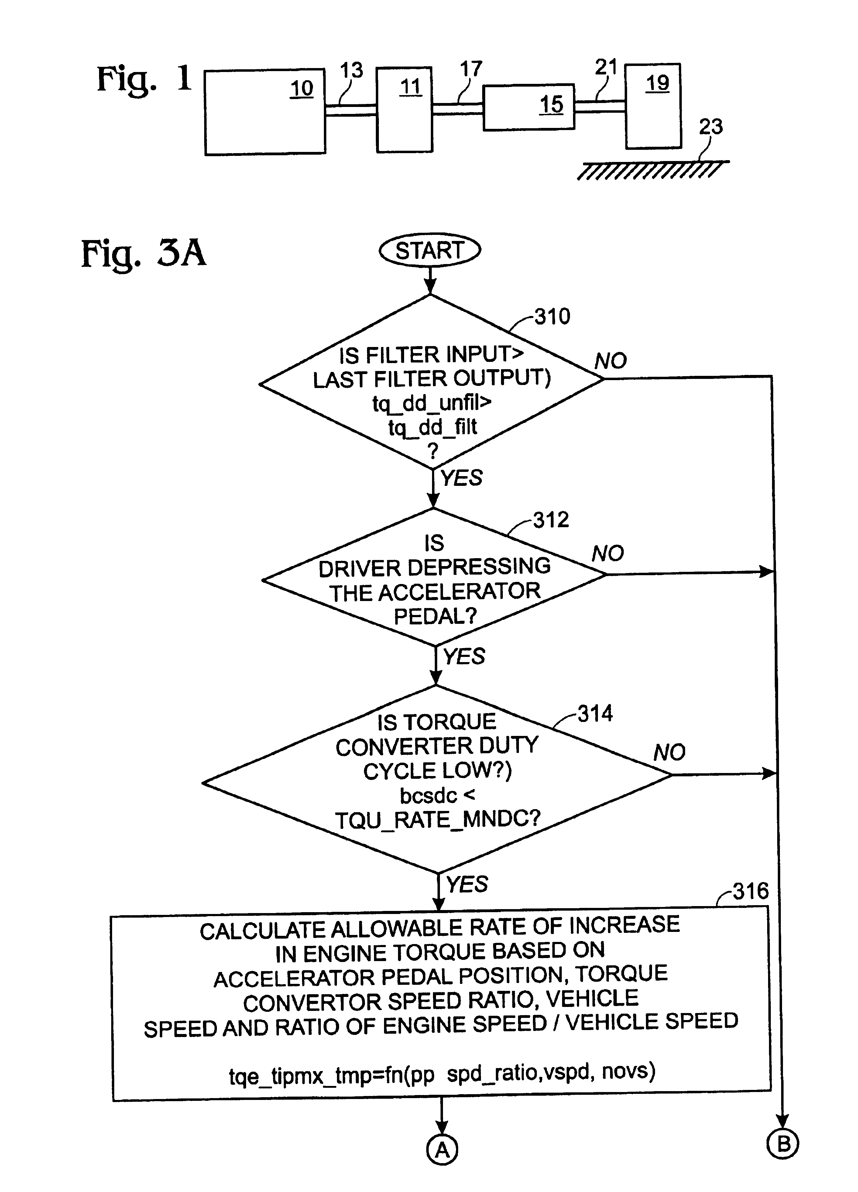
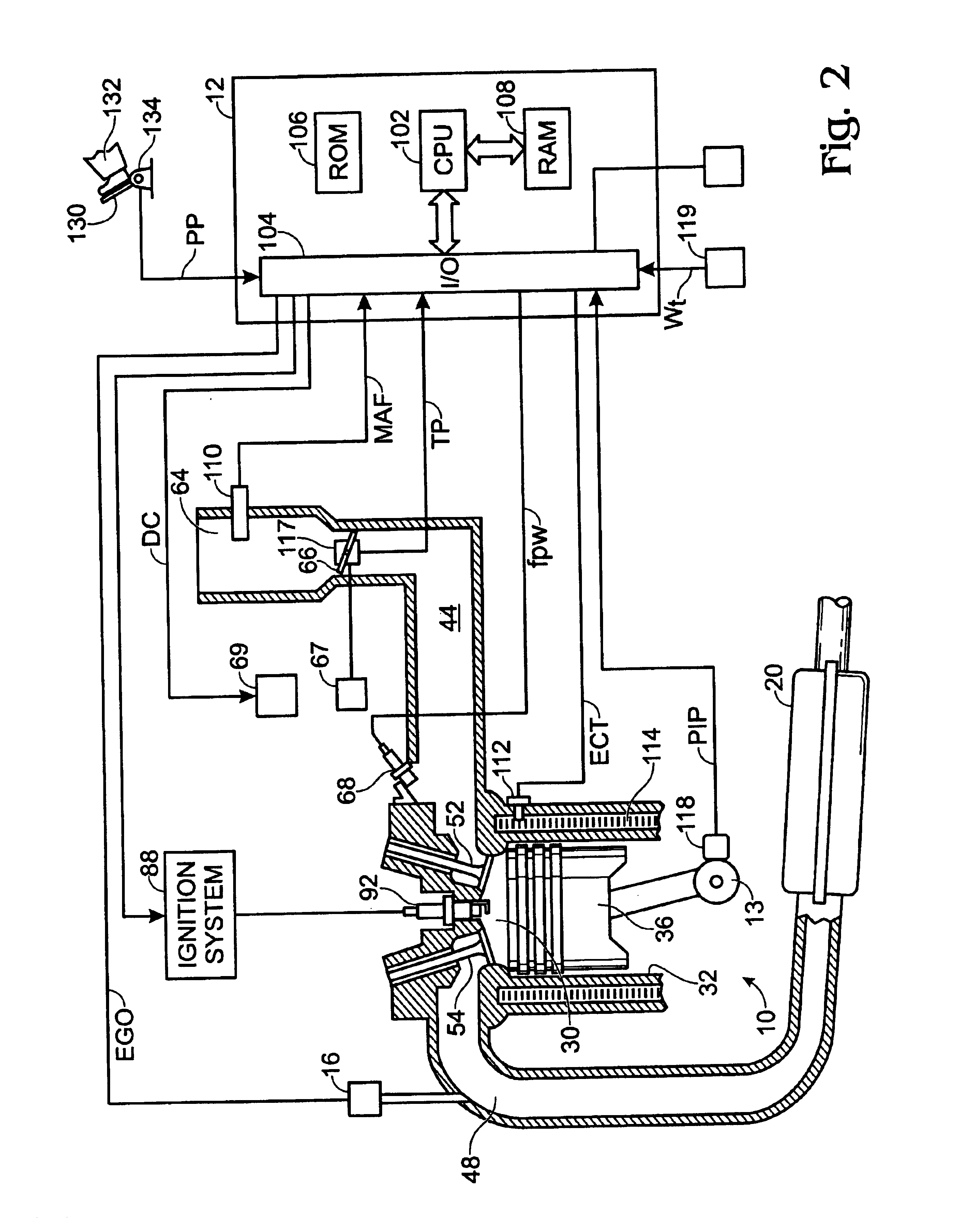
[0019]Referring to FIG. 1, internal combustion engine 10, further described herein with particular reference to FIG. 2, is shown coupled to torque converter 11 via crankshaft 13. Torque converter 11 is also coupled to transmission 15 via turbine shaft 17. Torque converter 11 has a bypass clutch (not shown) which can be engaged, disengaged, or partially engaged. When the clutch is either disengaged or partially engaged, the torque converter is said to be in an unlocked state. Turbine shaft 17 is also known as transmission input shaft. Transmission 15 comprises an electronically controlled transmission with a plurality of selectable discrete gear ratios. Transmission 15 also comprises various other gears, such as, for example, a final drive ratio (not shown). Transmission 15 is also coupled to tire 19 via axle 21. Tire 19 interfaces the vehicle (not shown) to the road 23. Note that in one example embodiment, this powertrain is coupled in a passenger vehicle that travels on the road.

[0...


PUM


Abstract

An engine control system controls engine torque to transition through the transmission and driveline's lash zone. The transmission and driveline's lash zone is indicated using information of the speed ratio across the torque converter. This information is then supplemented with information of the driver's request and vehicle speed so that engine torque is adjusted at various predetermined rates based on current operating conditions. As such, the system can reduce undesired drive feel that otherwise may occur as the system passes through the transmission and driveline's lash zone. By limiting the change of torque in this way, driveability, while at the same time maintaining acceptable performance response.

Description

FIELD OF THE INVENTION[0001]The present invention relates to a system and method to control an internal combustion engine coupled to a torque converter and in particular to adjusting engine output to improve drive feel while maintaining performance.BACKGROUND OF THE INVENTION[0002]Internal combustion engines are controlled in many different ways to provide acceptable driving comfort during all operating conditions. Some methods use engine output, or torque, control where the actual engine torque is controlled to a desired engine torque through an output adjusting device, such as with an electronic throttle, ignition timing, or various other devices.[0003]It is known that there is the potential for poor driveability when the vehicle operator releases and subsequently engages the accelerator pedal. Specifically, as described in U.S. Pat. No. 6,266,597, this results due to transmission or driveline gear lash. For example, when the engine transitions from exerting a positive torque to e...

Claims


Application Information

Patent Timeline
Patent Type & Authority Patents(United States)
IPC IPC(8): F02D41/02F02D41/10
CPCF02D41/0215F02D41/107Y10T477/679F02D2400/12Y10T477/675F02D2250/21
Inventor DOERING, JEFFREY A.CULLEN, MICHAEL J.CIARROCCHI, ROB
Owner FORD GLOBAL TECH LLC
Learn More