Composite elastomeric seal for sealing fluid lines

a technology of fluid line and composite elastomer, which is applied in the direction of sealing, engine seals, packaging, etc., can solve the problems of spiral failure during sealing operation, o-rings are prone to rolling during installation of rings, and the cost of such assemblies is relatively high, so as to achieve the effect of sealing two fluid line members

Inactive Publication Date: 2005-06-28
PRECIX
View PDF31 Cites 21 Cited by
  • Summary
  • Abstract
  • Description
  • Claims
  • Application Information

AI Technical Summary

Benefits of technology

[0015]providing a composite seal having a shaped contour with protruding lip sealing portions for effectively sealing two fluid line members together; and

Problems solved by technology

In general, conventional three-part sealing assemblies provide an effective seal; however, there are several disadvantages associated with such systems.
For example, the costs of such assemblies are relatively high, since three separate and distinct components must be installed in a specific configuration.
Further, O-rings are prone to rolling during installation of the rings.
Rolling of the O-rings can cause spiral failures during operation of the seal.

Method used


Image

  • Composite elastomeric seal for sealing fluid lines
  • Composite elastomeric seal for sealing fluid lines
  • Composite elastomeric seal for sealing fluid lines

Examples


Embodiment Construction

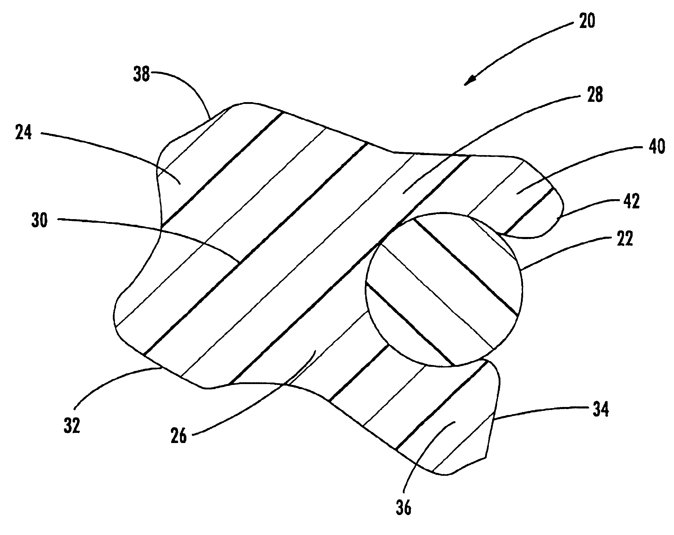
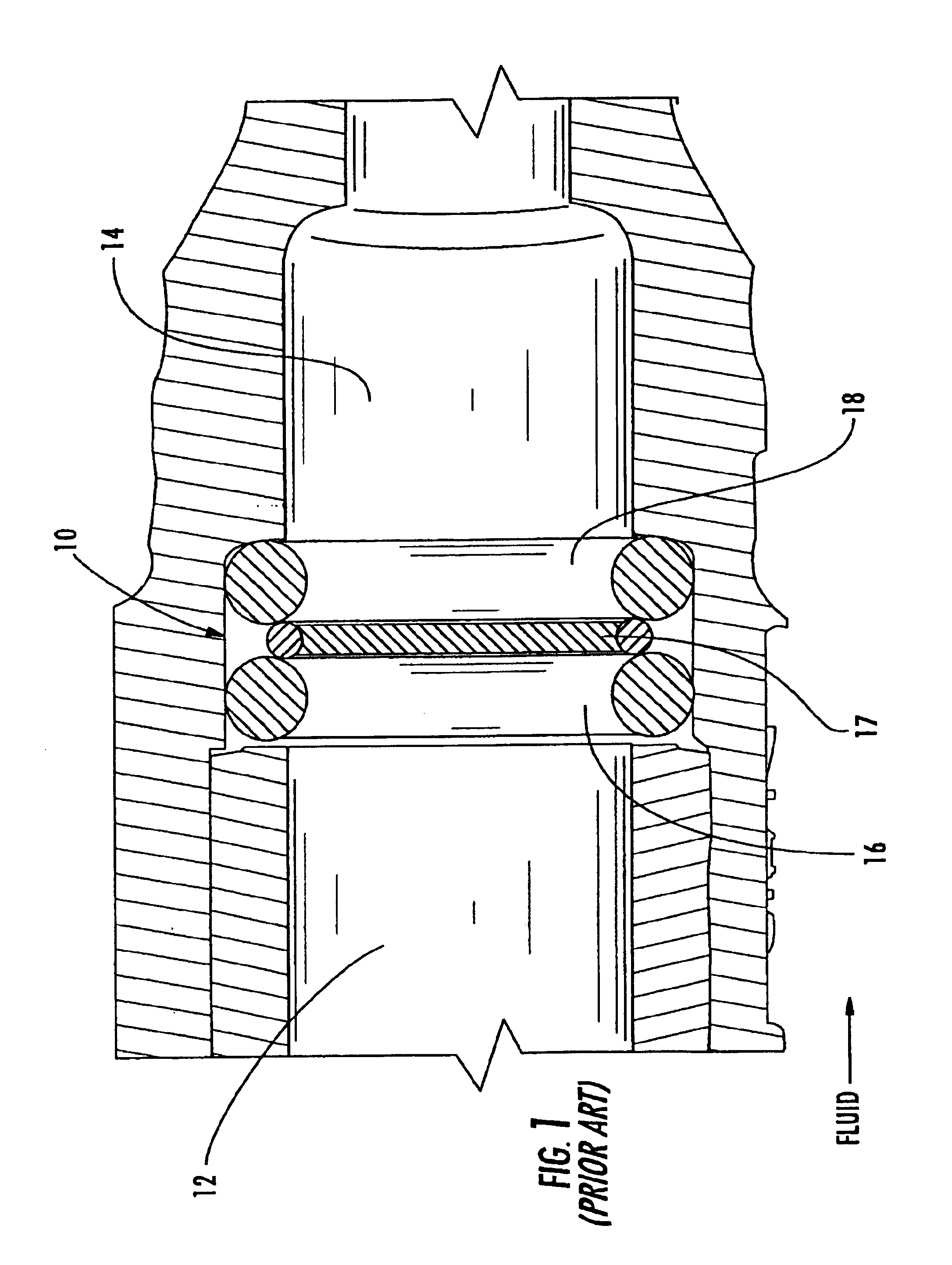
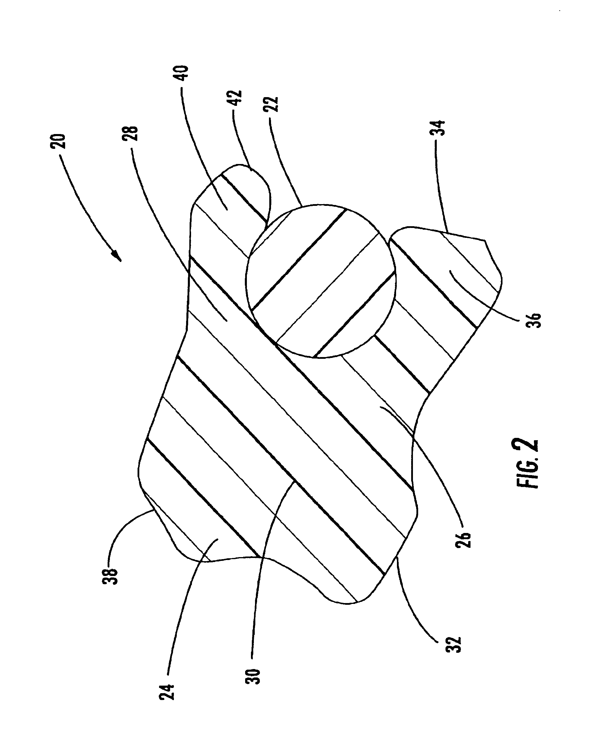
[0022]Referring to FIG. 1, a three-part sealing system of the prior art is generally indicated at 10. The sealing system 10 is used for sealing line members 12 and 14 which are coupled together. The sealing system 10 comprises O-rings 16 and 18 and a metal spacer 17. The O-ring 16 is typically made of a fluorocarbon material and positioned on the fluid-facing side of the sealing system 10. (In FIG. 1, the pressurized fluid is shown as flowing from the left side of the sealing assembly 10 as indicated by the direction of the arrow.) The O-ring 18 is located on the opposite side of the sealing system 10 and is typically made of a fluorosilicone material. These prior art sealing systems 10 provide a double-sealing effect. The secondary, fluorosilicone O-ring seal 18 acts as a secondary seal in the event that the primary, fluorocarbon O-ring seal 16 malfunctions. However, as discussed above, these prior art sealing systems 10 have several disadvantageous features including cost and inst...


PUM


Abstract

A composite elastomeric seal for sealing fluid line members is provided. The composite seal comprises an outer U-shaped seal body and an inner elastomeric portion. The U-shaped seal body comprises inner and outer extending arms, each arm having a shaped contour and two protruding lip portions. One set of lips of the outer seal wraps around the inner elastomeric portion, and the other set of lips provides an auxiliary seal for sealing the fluid line members together. The invention further includes sealing assemblies that employ the composite seals.

Description

CROSS-REFERENCE TO RELATED APPLICATIONS[0001]This application claims the benefit of U.S. Provisional Application No. 60 / 366,295 having a filing date of Mar. 20, 2002.BACKGROUND OF THE INVENTION[0002]The present invention relates generally to sealing rings for sealing machinery lines together. More particularly, the present invention relates to an improved “U-shaped” composite elastomeric seal for sealing together fluid line members such as fuel injection lines and fuel ports.[0003]The industry uses sealing rings and gaskets in various applications for sealing fluid lines such as gas lines, chemical lines, hydraulic cylinders, and the like. For example, “O-rings” are commonly used in fluid sealing systems. Particularly, conventional sealing systems can comprise three components: a) an O-ring made from a fluorocarbon material; b) a metal spacer; and c) an O-ring made from a fluorosilicone material.[0004]A conventional three-part sealing system using O-rings and a metal spacer is shown...

Claims


Application Information

Patent Timeline
Patent Type & Authority Patents(United States)
IPC IPC(8): F16J15/32
CPCF16J15/3236Y10S277/934
Inventor MALONE, CAROLMAHER, DONALD
Owner PRECIX
Why Eureka
Try Eureka