
Caddy

a positioning system and caddy technology, applied in the field of positioning systems, can solve the problem of no short-range positioning system that makes use of radio frequency, and achieve the effect of simple and easy use, inexpensive manufacturing and us

Inactive Publication Date: 2005-06-21
GARD ADAM
View PDF3 Cites 136 Cited by
  • Summary
  • Abstract
  • Description
  • Claims
  • Application Information

AI Technical Summary

Benefits of technology

[0014]Another object of the present invention is to provide a golf ball positioning system wherein the detection unit is able to keep track of a plurality of golf balls each golf ball transmitting signals at a different frequency.
[0016]Yet a further object of the present invention is to provide a golf ball positioning system wherein the detection unit is able to automatically calculate the score of the golfer 8 playing with the golf ball being tracked.
[0017]Still another object of the present invention is to provide a golf ball positioning system wherein the detection unit vibrates when a user is within a predetermined distance of the golf ball.
[0018]Another object of the present invention is to provide a golf ball positioning system that is simple and easy to use.
[0019]Still yet another object of the present invention is to provide a golf ball positioning system that is inexpensive to manufacture and use.

Problems solved by technology

However, there are no short range positioning systems that make use of a radio frequency to detect the position of a golf ball.

Method used


Image

  • Caddy
  • Caddy
  • Caddy

Examples


Embodiment Construction

[0035]The following discussion describes in detail one embodiment of the invention. This discussion should not be construed, however, as limiting the invention to those particular embodiments. Practitioners skilled in the art will recognize numerous other embodiments as well. For definition of the complete scope of the invention, the reader is directed to appended claims.

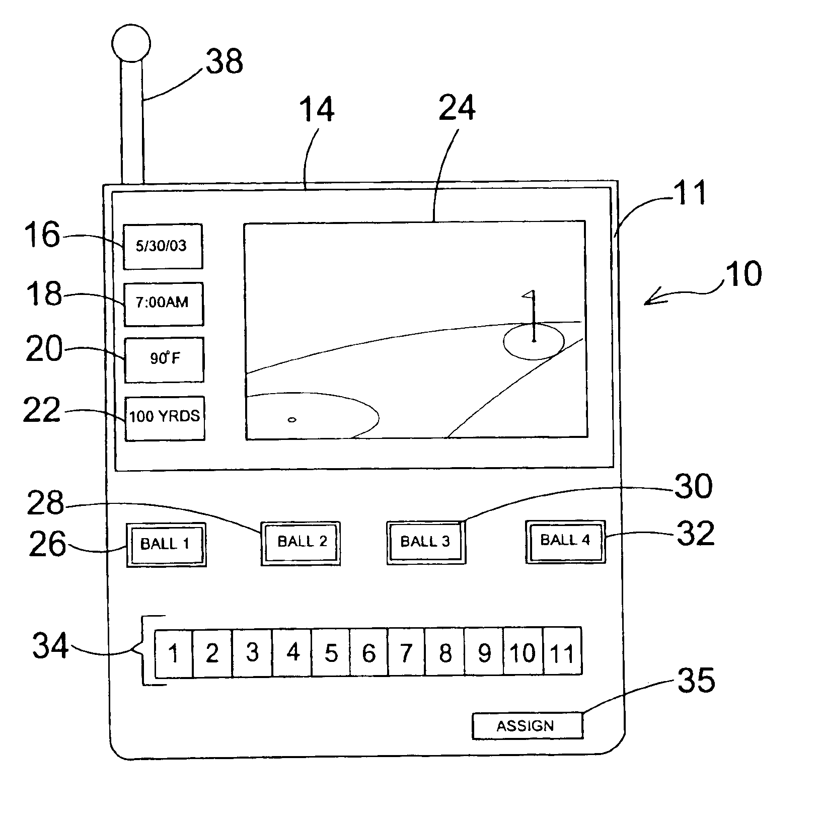
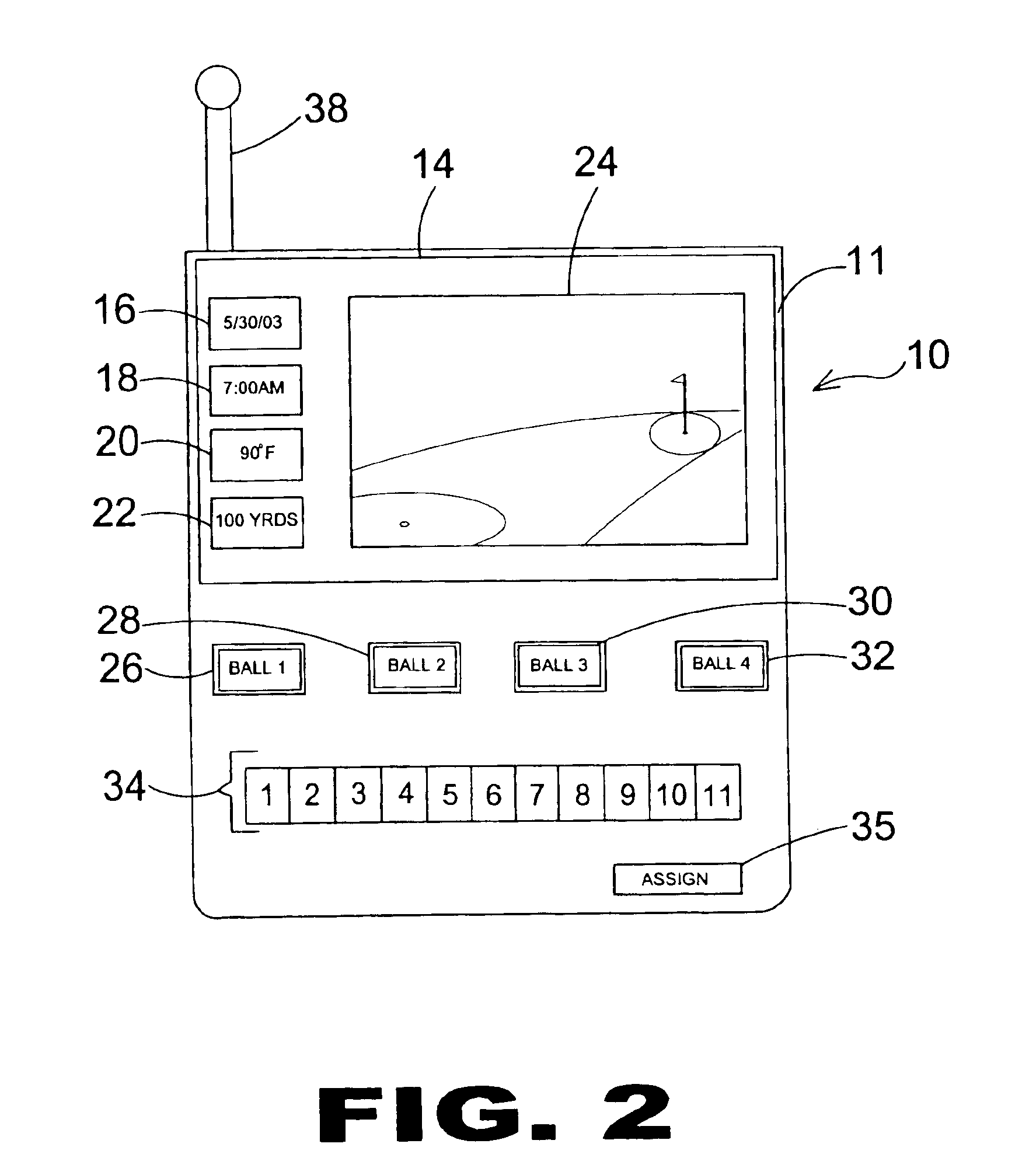
[0036]Turning now descriptively to the drawings, in which similar reference characters denote similar elements throughout the several views, FIGS. 1 through 9 illustrate a golf ball positioning system of the present invention indicated generally by the numeral 10.

[0037]FIG. 1 is an illustrative view of the golf ball positioning system 10 of the present invention being used to determine the position of a golf ball on a golf course 2. Shown in FIG. 1 is a golfer 8 on a golf course 2 looking for a golf ball 12 that has been hit off the fairway 7 into the woods 6. The golfer 88 is unsure of the position of the golf ball...


PUM


Abstract

The present invention discloses a positioning system for determining the position of a golf ball. The golf ball positioning system includes a golf ball having a first transmitter positioned therein for transmitting a position signal. The system further includes a detection until having a first processor, a first receiver and a display. The first receiver and display are both connected to the first processor. The position signal is transmitted by the transmitter and is received by the first receiver and processed by the first processor. Upon processing the position signal, directional instructions are generated for display on the display and provide aid to the user in locating the position of the golf ball.

Description

BACKGROUND OF THE INVENTION[0001]1. Field of the Invention[0002]The present invention relates generally to positioning systems, and more specifically, to a positioning system that detects the position of a golf ball on a golf course. The positioning system includes a golf ball having a computer chip with a transmitter and receiver able to receive signal having a unique frequency. A map unit assigns the frequency the ball and upon the ball being hit, the map unit displays directional instructions to a handheld unit retained by the user to assist the user in locating the position of the golf ball.[0003]2. Description of the Prior Art[0004]Numerous other positioning systems exist in the prior art. Generally, these prior art positioning systems includes a computerized device that send information to and receive information from a satellite which allows the person to be located and tracked by a third party. These global positioning systems are used often in tracking the path of employees...

Claims


Application Information

Patent Timeline
Patent Type & Authority Patents(United States)
IPC IPC(8): A63B57/00A63B43/00A63B71/06
CPCA63B24/0021A63B57/00A63B71/06A63B43/00A63B2024/0053A63B2243/0029A63B2071/0691A63B2220/12A63B2220/20A63B2225/54A63B2071/0636A63B2102/32
Inventor GARD, ADAM
Owner GARD ADAM
Learn More