
Connector package with supporting walls

a technology of connecting wall and supporting wall, which is applied in the field of packaging, can solve the problems of prone to damage or even destruction of socket connectors b>8/b>, and achieve the effect of reducing the risk of accidental damage to the connector installed

Inactive Publication Date: 2005-06-21
HON HAI PRECISION IND CO LTD
View PDF3 Cites 5 Cited by
  • Summary
  • Abstract
  • Description
  • Claims
  • Application Information

AI Technical Summary

Benefits of technology

[0006]An object of the present invention is to provide an electrical connector package having strong supporting portions that minimize the risk of accidental damage to connectors installed therein.
[0007]Another object of the present invention is to provide an electrical connector package which is light and easily manufactured.
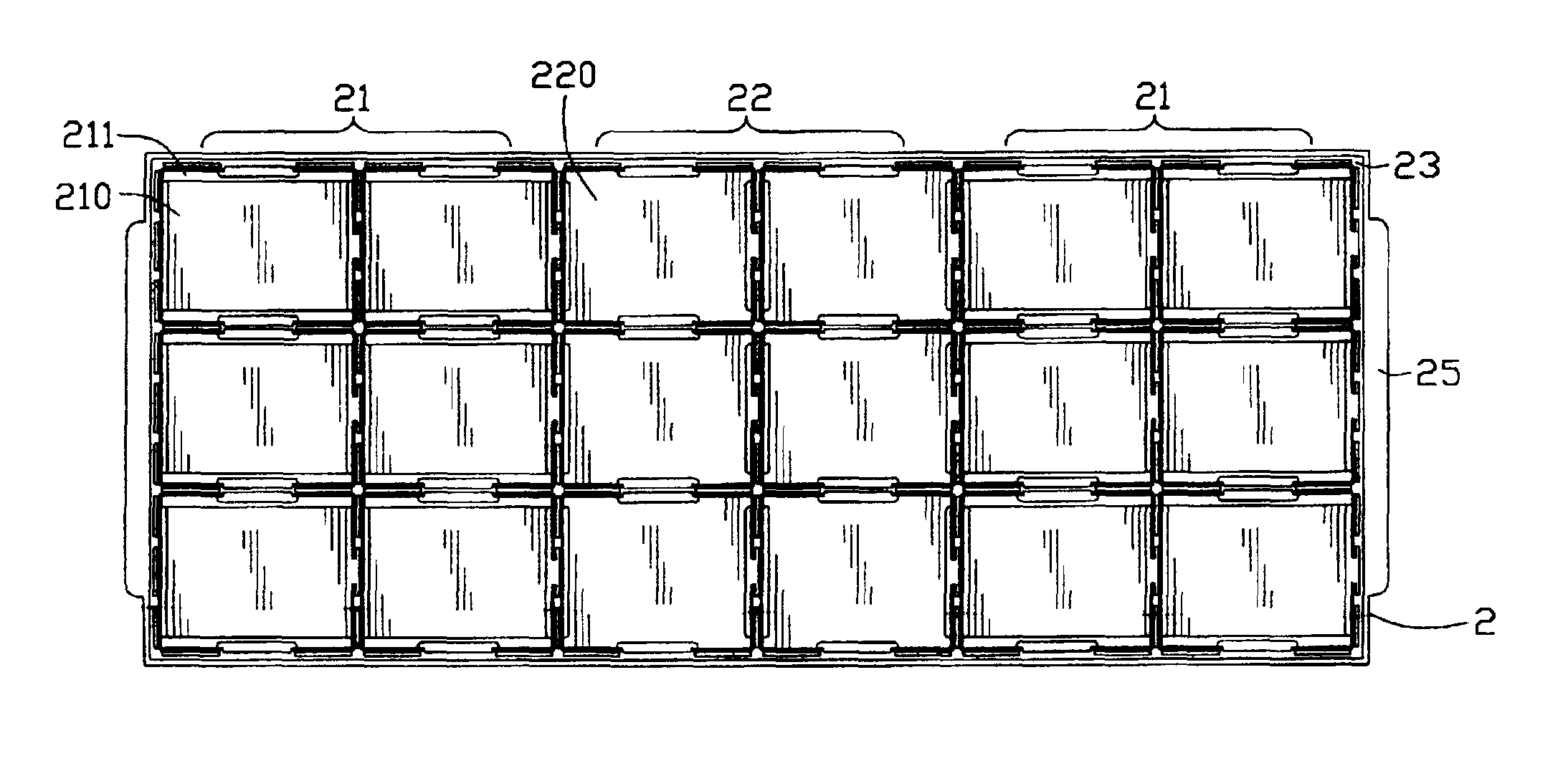
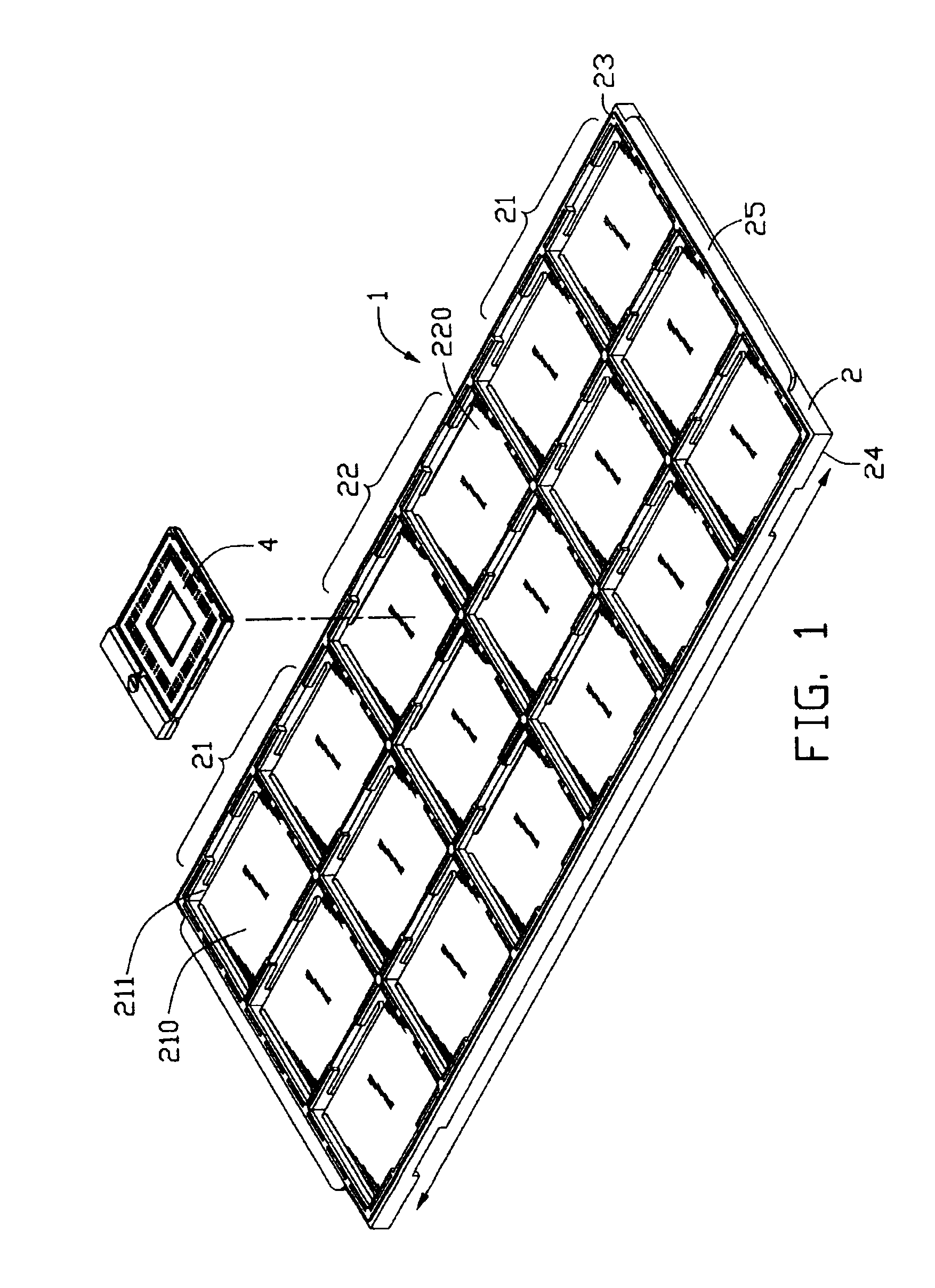
[0008]To achieve the above objects, a package of the present invention for receiving a plurality of electrical socket connectors comprises an elongate housing. The housing comprises a set of first supporting portions in each of opposite ends thereof, and a set of second supporting portions between the two sets of first portions. Each set of first portions and the set of second portions are each arranged in an array. Each first portion comprises a rectangular bottom wall. A pair of through slots is defined in the bottom wall at opposite longitudinal sides respectively of the first portion. The set of second portions comprises a single bottom wall that spans an entire area of all the second portions. The socket connectors are fittingly received in the first portions and the second portions so that they abut the respective bottom walls. The bottom walls of the first portions and the bottom wall of the second portions cooperatively render the package strong enough to resist deformation. Thus the risk of damage to the socket connectors mounted in the package is minimized.

Problems solved by technology

When this happens, the socket connectors 8 are prone to be damaged or even destroyed.

Method used


Image

  • Connector package with supporting walls
  • Connector package with supporting walls
  • Connector package with supporting walls

Examples


Embodiment Construction

[0014]Reference will now be made to the drawings to describe the present invention in detail.

[0015]Referring to FIG. 1, a package 1 in accordance with a preferred embodiment of the present invention is used for packaging a plurality of electrical socket connectors 4 (only one shown). The socket connectors 4 are used for connecting central processing units (CPUs) to printed circuit boards (PCBs) in personal computers (PCs).

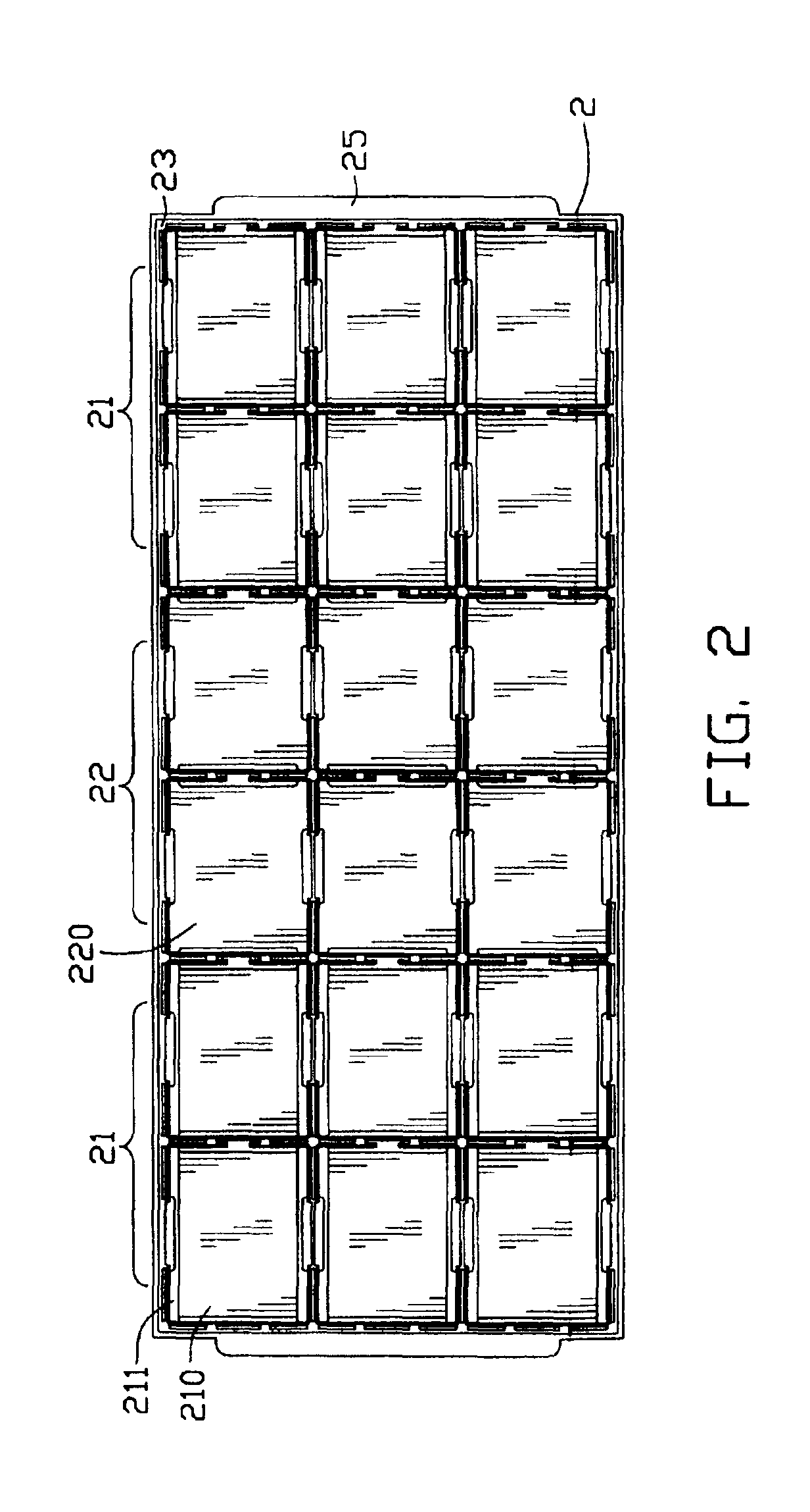
[0016]Referring to FIGS. 1 and 2, the package 1 comprises an elongate housing 2. The housing 2 has a top surface 23 via which the socket connectors 4 are normally mounted into the package 1, and a bottom surface 24 opposite to the top surface 23. The housing 2 includes a set of first supporting portions 21 in each of opposite ends thereof, and a set of second supporting portions 22 between the two sets of first portions 21. Each set of first portions 21 and the set of second portions 22 are each arranged in an array having two columns and three rows. Thus, the pack...


PUM


Abstract

A package (1) for receiving a plurality of electrical socket connectors (4) comprises an elongate housing (2). The housing includes a set of first supporting portions (21) in each of opposite ends thereof, and an intermediate set of second supporting portions (22) between the two sets of first portions. Each first portion includes a rectangular bottom wall (210). A pair of through slots (211) is defined in the bottom wall at opposite longitudinal sides respectively of the first portion. The set of second portions comprises a single bottom wall (220) that spans an entire area of all the second portions. The socket connectors are fittingly received in the first portions and the second portions so that they abut the respective bottom walls. The bottom walls of the first portions and the bottom wall of the second portions cooperatively render the package strong enough to resist deformation.

Description

BACKGROUND OF THE INVENTION[0001]1. Field of the Invention[0002]The present invention relates to a package, and particularly to a package used for receiving electrical connectors therein and providing easy and safe transportation and handling of the connectors.[0003]2. Description of the Prior Art[0004]Delicate electronic components, such as CPU sockets, are often packaged into trays that are stacked into freight containers for transportation, as disclosed in “Technology Analysis of Electrical Connector” (Connector Specifier, February 2001, pp.18-20). Such tray packages each generally have an elongate housing comprising a plurality of supporting portions. The supporting portions are arranged in an array for respectively receiving CPU sockets therein. Some of the supporting portions comprise bottom walls, while others do not. Referring to FIGS. 3 and 4, a conventional CPU socket connector package 9 comprises an elongate housing 91 having a plurality of supporting portions defined the...

Claims


Application Information

Patent Timeline
Patent Type & Authority Patents(United States)
IPC IPC(8): H05K7/10H05K13/00
CPCH05K13/0084H05K7/10
Inventor WANG, WENXIN
Owner HON HAI PRECISION IND CO LTD
Learn More