
Haptic shifting devices

a shifting device and haptic technology, applied in the direction of mechanical control devices, gearing, manual control with single controlling member, etc., can solve the problems of unintuitive or less precise control, limited to a particular implementation of physical control, etc., and achieve the effect of effective user control over gear selection and other operations

Inactive Publication Date: 2005-06-14
IMMERSION CORPORATION
View PDF110 Cites 131 Cited by
  • Summary
  • Abstract
  • Description
  • Claims
  • Application Information

AI Technical Summary

Benefits of technology

[0005]To alleviate some of the problems in existing shift-by-wire systems, the inventions disclosed herein provide haptic sensations for a shift-by-wire system. Haptic sensations allow a great range of programmed control schemes and patterns in a control and can provide more effective user control over gear selection and other operations.
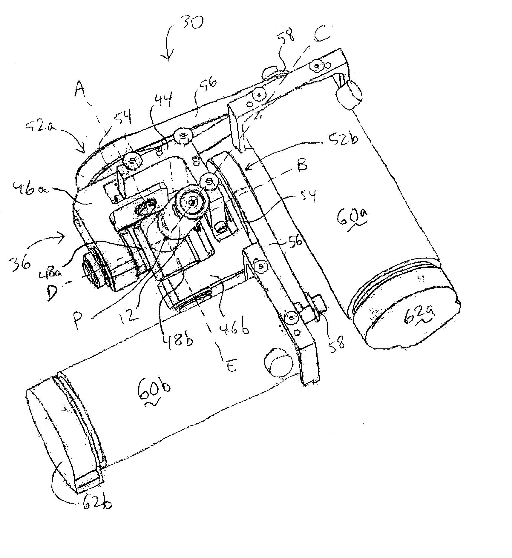
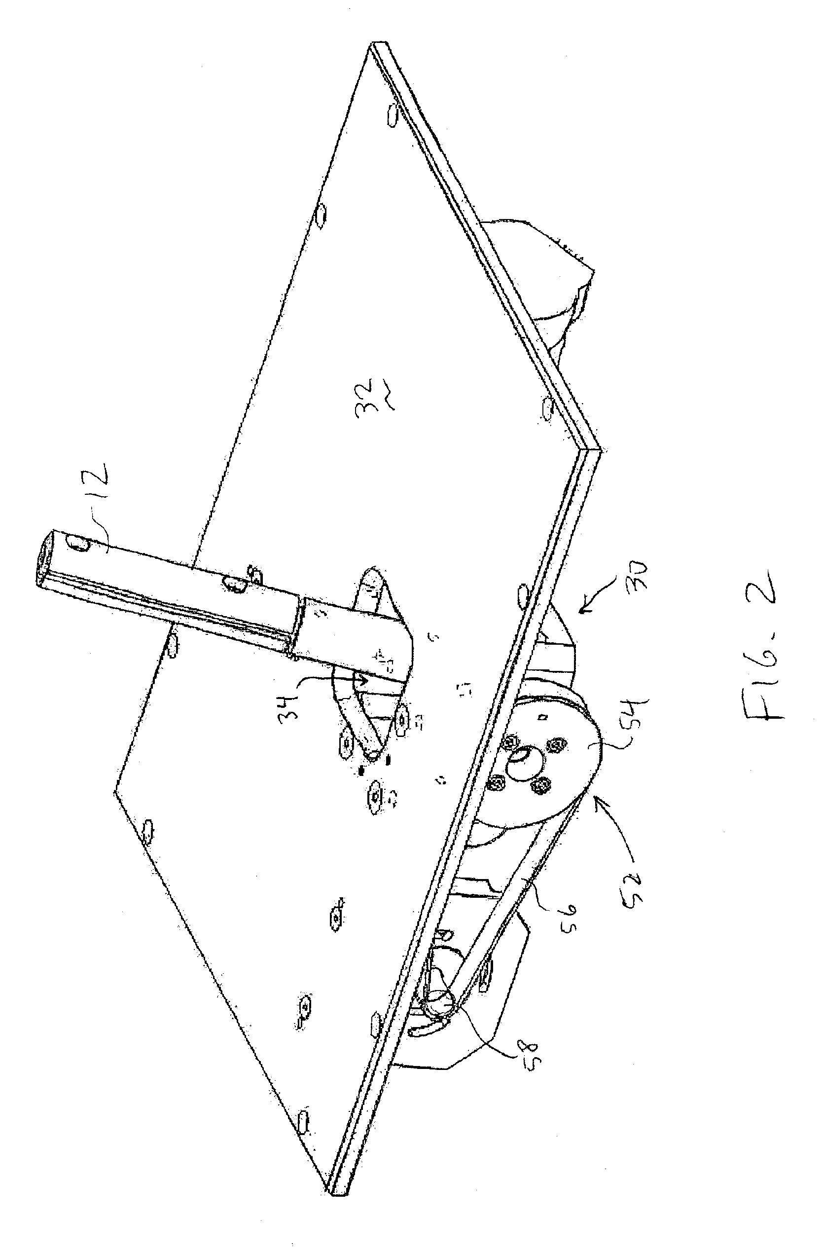
[0011]The present inventions provide a haptic shift device that allows haptic sensations to be output to the user of a shift-by-wire system in a vehicle. The haptic shift device provides forces that assist in implementing barriers to the shift lever, as well as allowing programming variability to the device. For example, several different shift patterns can be provided and can be selectable by the user. Furthermore, haptic sensations output on the shift lever assist the user in shifting tasks and can provide mechanical cues in a shift-by-wire system.

Problems solved by technology

One problem with existing shift-by-wire systems is that they are still limited to a particular implementation of the physical control manipulated by the user.
Furthermore, shift-by-wire controls do not offer the user some of the cues of mechanical systems in controlling shifting, which may cause the control to be unintuitive or less precise.

Method used


Image

  • Haptic shifting devices
  • Haptic shifting devices
  • Haptic shifting devices

Examples


Embodiment Construction

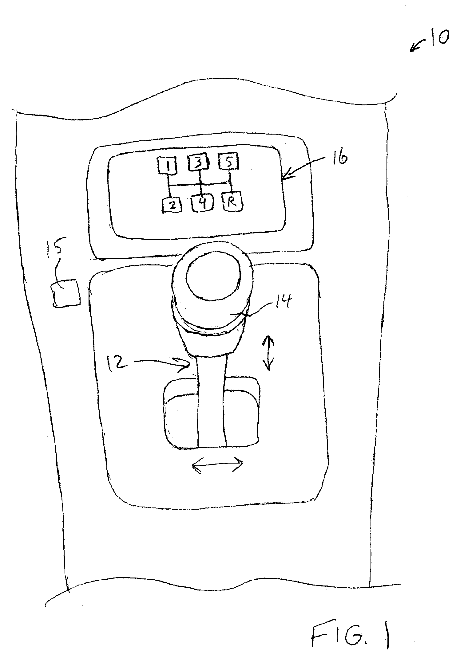
[0019]FIG. 1 is a perspective view of an example of a haptic shift device 10 for a vehicle. Shift device 10 is implemented in FIG. 1 similar to a standard gearshift lever as found in automobiles with manual transmission. For example, the shift device 10 can be located between the front seats in an automobile to allow the driver easy access to the shift device while driving.

[0020]Haptic shift device 10 includes a shift lever 12 including a grip 14 which is grasped or otherwise physically contacted by the user and moved by the user in one or more directions to control the gear of the transmission of the vehicle. The position of the shift lever determines in which transmission gear the vehicle is present engaged. Since the device is integrated in a shift-by-wire system, the shift lever is not mechanically coupled to the transmission of the vehicle, but is instead connected to an electronic interface and system that can read the position of the lever and control the transmission in resp...


PUM


Abstract

A haptic shift device for use in shift-by-wire systems in vehicles. The haptic shift device includes a shift lever manipulatable by a user. At least one sensor detects a position of the shift lever, and a transmission gear of the vehicle is caused to be changed based on the position of the shift lever. At least one electrically-controlled actuator outputs a force on the shift lever. In some embodiments, the shift lever is moveable within a pattern and is blocked from areas outside the boundaries of the pattern. The actuator(s) can be active or passive, and / or a variable mechanical gate can be used to implement the pattern. Provided shifting modes can include automatic, manual, and / or sequential modes. Other shifting modes can also be provided.

Description

BACKGROUND OF THE INVENTION[0001]This invention relates generally to haptic feedback devices, and more particularly to haptic feedback interface devices used in conjunction with mechanical devices allowing desired manipulation of the interface device.[0002]Control of a vehicle through the use of electronically-controlled mechanisms rather than mechanically-controlled mechanisms has been implemented in several different forms. Typically called “steer-by-wire,”“drive-by-wire,” or “control-by-wire”, this form of control allows the user to direct electric motors and / or hydraulic or pneumatic control systems, to perform mechanical operations rather than the user directly performing the mechanical operations using a mechanism. For example, in a standard mechanical steering mechanism in an automobile, the user moves a steering wheel, which mechanically rotates rods, gears, and other mechanical parts to turn the front wheels based on the motion of the steering wheel. In a drive-by-wire syst...

Claims


Application Information

Patent Timeline
Patent Type & Authority Patents(United States)
IPC IPC(8): F16H59/04F16H61/24F16H59/10B60K20/02G05G9/047
CPCF16H59/044F16H61/24F16H59/105G05G2009/04766Y10T74/20159F16H2061/242Y10T74/20201Y10T74/2003F16H2061/241B60K20/00
Inventor LEVIN, MICHAEL D.VASSALLO, STEVEN P.
Owner IMMERSION CORPORATION
Learn More