
Storage system making possible data synchronization confirmation at time of asynchronous remote copy

a data synchronization and remote copy technology, applied in data processing applications, instruments, fault response, etc., can solve the problems of data which is left in the disk array device and has not been transferred yet, the host of the local side is difficult to confirm the completion of the synchronization of the host write, and the data is los

Inactive Publication Date: 2005-06-07
HITACHI LTD
View PDF7 Cites 7 Cited by
  • Summary
  • Abstract
  • Description
  • Claims
  • Application Information

AI Technical Summary

Benefits of technology

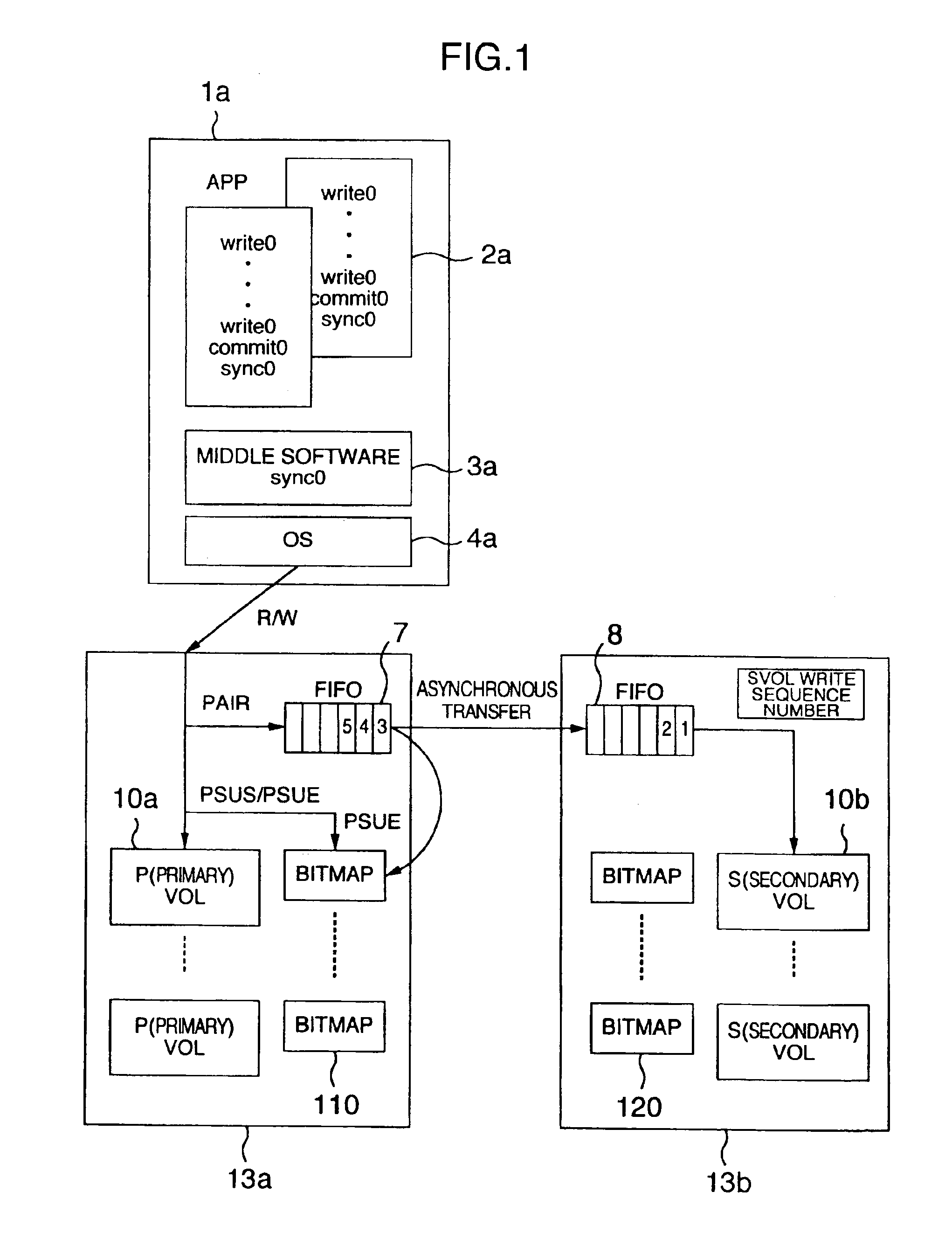
[0012]First, the case where one storage system is connected to a computer will now be described. If an application of the computer executes a write command (request), then typically data of the write command is simply written into a data buffer included in the computer, in such a state that there is not a commit command. Data in the data buffer does not coincide with data in the storage system. If thereafter the application issues a commit command, then the data in the data buffer is actually written in the storage system by a write command. Thereafter, the storage system stores write data in a cache memory. (At this time point, the data in the storage system coincides with the data in the computer.) Thereupon, the storage system acknowledgements the computer which has issued the write command, with write request completion. Upon confirming the write request completion, the computer returns an acknowledgement for the commit command to the application. By means of this return, the application knows that the data in the storage system coincides with the data in the computer.
[0013]Subsequently, the case where asynchronous remote copy is being conducted will now be described. If an application of the computer issues a commit command, then data in the data buffer is written into a cache of the storage system of the local side by a write command. As its acknowledgement, the storage system of the local side returns write completion to the computer.

Problems solved by technology

Therefore, it is difficult for the host of the local side to confirm the completion of synchronization of the host write request to the remote side (i.e., determine whether data generated by the host write request has been transferred positively to the disk array device of the remote side).
Furthermore, from the viewpoint of data recovery at the time of a disaster, there is a problem that data which are left in the disk array device and which have not been transferred yet are lost because of a fault of a primary site (main site), and it is impossible to know assured data after takeover to a secondary site (back-up site) is conducted and operation is started in the secondary site.
However, the asynchronous transfer system of the above described conventional technique does not have a synchronization confirmation method for a host I / O because of inherent characteristics of asynchronous transfer.

Method used


Image

  • Storage system making possible data synchronization confirmation at time of asynchronous remote copy
  • Storage system making possible data synchronization confirmation at time of asynchronous remote copy
  • Storage system making possible data synchronization confirmation at time of asynchronous remote copy

Examples


first embodiment

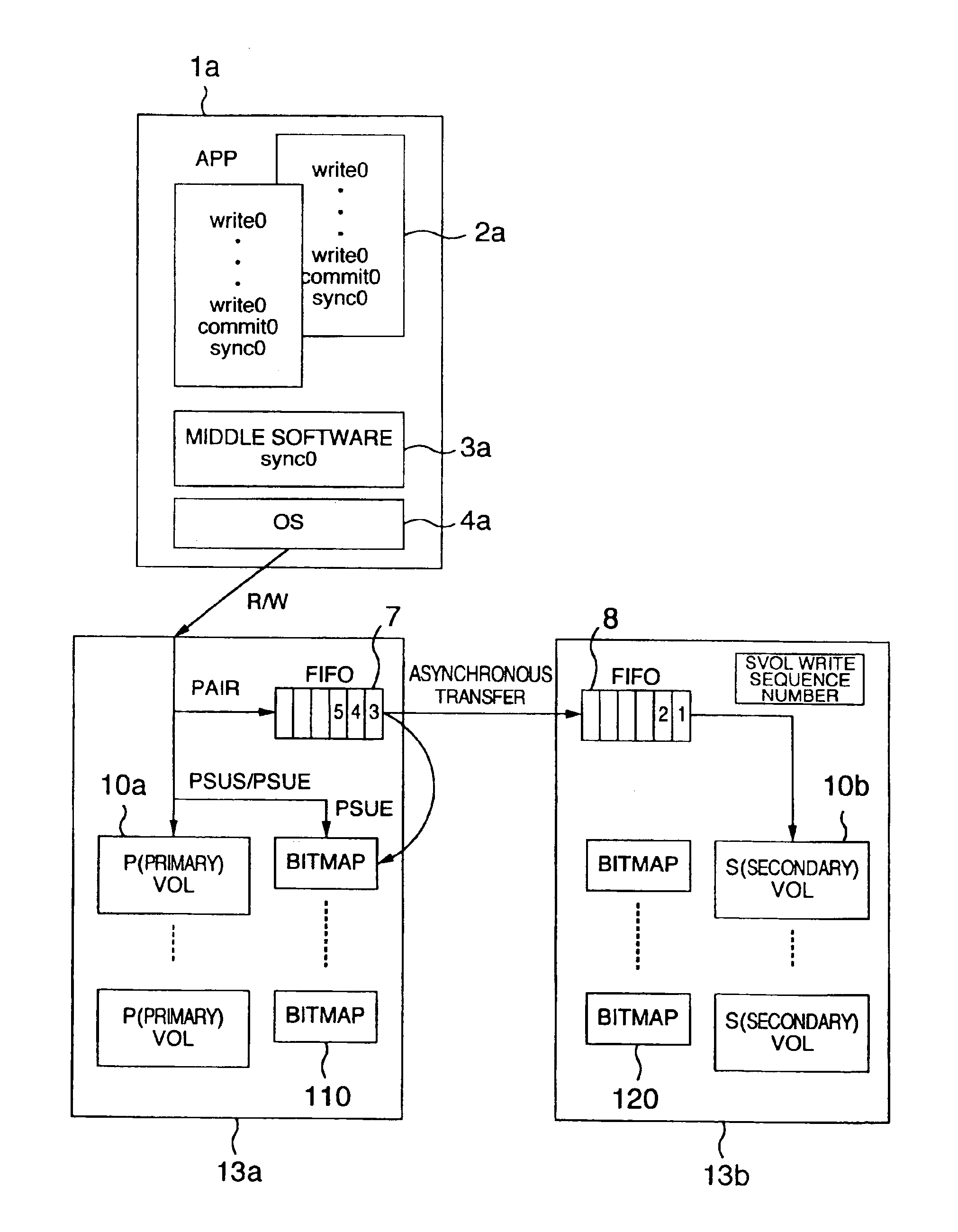
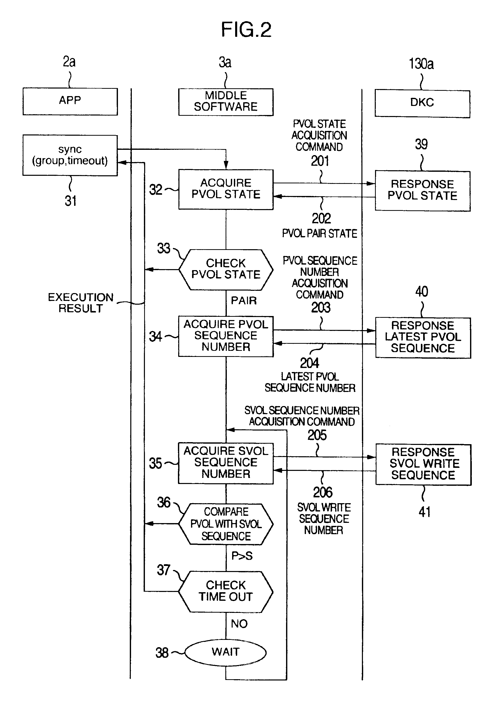
[0024]Hereafter, the present invention will be described in detail by referring to FIGS. 1 to 3. First, a system configuration example to which the present invention is applied will be described by referring to FIG. 3. FIG. 3 is a system block diagram showing the whole configuration of a typical HA cluster. In the ensuing description, it is assumed that a disk array device 13a is a local device (or a primary site) and a disk array device 13b is a remote device (or a secondary site or back-up site). Furthermore, it is assumed that reference numerals with “a” added thereto represent the local side and reference numerals with “b” added thereto represent the remote side.

[0025]Host computers 1a and 1b forming an HA cluster include APPs (application programs) 2a and 2b such as databases, middle software 3a and 3b, OSs (operating systems) 4a and 4b for controlling the APP and middle software, and I / O I / Fs (input output interfaces) 23a and 23b each for controlling input and output of a comm...

second embodiment

[0071]FIGS. 4 and 5 show the present invention in which control of the middle software 3a is effected in the large-sized disk array device 13a for the purpose of reducing the load of middle software control of the host device 1a.

[0072]FIG. 4 is a logical block diagram of a storage system according to the second embodiment of the present invention, where middle software control described by referring to FIGS. 1 and 2 is effected in the large-sized disk array device. FIG. 4 is substantially the same in logical configuration as FIG. 1 except that the function implemented by the middle software 3a of FIG. 1 is replaced by sync control 300 (described later) of FIG. 4. The function of the sync control 300 is implemented by executing a program for implementing the present function in the “host I / F control circuit (17a)” or the “remote I / F control circuit (18a).”

[0073]The APP 2a in the host 1a conducts writing into the database as a transaction in the same way as the above described embodi...


PUM


Abstract

A synchronization confirmation method required for operation of a database is provided to a host device connected to a disk device which provides remote asynchronous data transfer. Immediately after commit of write data, an application of the host device issues a sync command which requires synchronization confirmation. A disk control device notifies the host device of a number concerning latest data received from the host device of a local side and a number concerning latest data received by a remote side. When the two numbers have coincided with each other, the host device judges the commit operation to have been completed.

Description

[0001]This is a continuation application of U.S. Ser. No. 10 / 424,932 filed Apr. 29, 2003; now U.S. Pat. No. 6,760,824 application of U.S. Ser. No. 09 / 663,205, filed Sep. 18, 2000, now U.S. Pat. No. 6,591,351.BACKGROUND OF THE INVENTION[0002]The present invention relates to data synchronization control in asynchronous remote copy between disk control devices.[0003]In computer systems of recent years, basic business of banks and stock companies has been shifted from centralized management using a large sized computer to a distributed database system (DDBMS) around a client / server system. In such a distributed database system environment, there is adopted an HA (High Availability) cluster configuration for processing data by using a plurality of servers and disk array devices in response to a client request. In such an HA cluster configuration, there is adopted a method of duplicating data between data centers located in remote places by way of precaution against a disaster such as an ...

Claims


Application Information

Patent Timeline
IPC IPC(8): A01H5/02G06F11/14G06F11/20
CPCG06F11/2074Y10S707/99955Y10S707/99953
Inventor URABE, KIICHIROURATANI, IKUO
Owner HITACHI LTD
Learn More