
Antenna device

a multi-band antenna and antenna technology, applied in the field of antenna devices, can solve the problems of difficult control of radio conductance, not well suited for multi-band applications, and much less than could be expected by wheelers limitations, and achieves easy and inexpensive manufacturing, increased coupling, and narrow bandwidth

Inactive Publication Date: 2005-06-07
LAIRD TECH AB (SE)
View PDF8 Cites 24 Cited by
  • Summary
  • Abstract
  • Description
  • Claims
  • Application Information

AI Technical Summary

Benefits of technology

[0015]A further object is to provide an antenna device that is easy and inexpensive to manufacture.
[0016]The invention is based on the realization that the coupling to the supporting structure is a critical factor for getting a usable band width of the frequency bands and that the bandwidth is narrowed by the fact that the phase of the signals is spread too much across the surface of the antenna element. As compared to prior art there are provided elements that increase the coupling to the support structure, which is the phone itself. By this increased coupling less current amplitudes will be needed for a specified useful power giving better bandwidth and less near zone losses. Also, by giving the antenna element or reed suitable coupling to a support structure, the phase of the signals can be kept within a sufficient range.

Problems solved by technology

However, one problem with a typical PIFA is that the radiation conductance is difficult to control.
Another problem with the original PIFA is that it is not well suited for multi-band applications, partly because the PIFA by definition is planar.
The result is however much less than could be expected by Wheelers limitation.
Thus, in the modified PIFA a large number of different patterns derived from I and C quoted above have been used but more or less of them have given limited results.

Method used


Image

  • Antenna device
  • Antenna device
  • Antenna device

Examples


first embodiment

[0044]an antenna device according to the invention will now be described with reference to FIG. 6, which is a schematic side view of a Loaded Reed Antenna (LRA). The antenna, generally designated 2, comprises a generally planar conduction element or reed 10. The reed 10 is positioned spaced apart from a support structure, generally designated 20. The support structure typically comprises a printed circuit board with circuits for a radio communication device in which the antenna is mounted. The projected surface of the supporting structure 20 is preferably 0.01-0.5 λ2, more preferably 0.03-0.25 λ2, and most preferably 0.05-0.10 λ2, wherein λ prefers to the used wavelength and the direction of projection is perpendicular to the general extension of the support structure. This provides for a better bandwidth compared to what would be obtained with a larger grounding plane. The effective antenna is generally the supporting structure itself so any means to enhance the coupling between th...

second embodiment

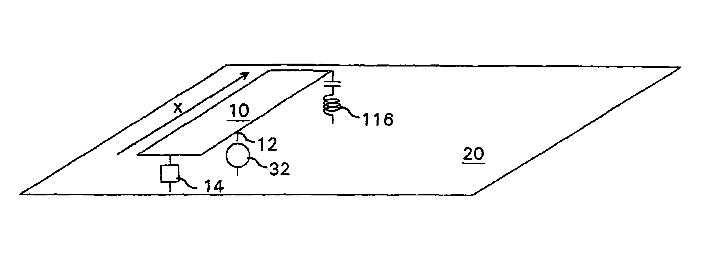
[0058]an antenna device according to the invention will now be described with reference to FIG. 8, which is a view similar to that of the first embodiment shown in FIG. 6. Like part in the two figures have been given the same reference numerals.

[0059]Thus, the LRA shown in FIG. 8 comprises a reed 10 with an input connection 12 connected to a feed source 32. There is also a support structure 20 spaced apart from the reed 10.

[0060]However, in contrast to the first embodiment, the load 18 is omitted. Also, there are loading impedances 114, 116 at both ends of the reed. This creates a current loop giving a magnetic coupling to further increasing the coupling to the support structure provided the phase is properly chosen.

[0061]The LRA is a multi-band antenna, preferably a dual band antenna. In such antennas, both frequency bands must work properly. One way to obtain that is to provide an impedance as a series resonance circuit.

[0062]Thus, in this second embodiment the load 116 is provide...


PUM


Abstract

An antenna device is adapted for use in at least two frequency bands, wherein the mean wave length of the higher of said frequency bands is λ. The antenna device comprises an antenna element in the form of a reed (10) mounted on a conductive support structure (20) having a projected area of less than λ2. The reed comprises a feeding portion (12) connectable to a feed device (32) and at least one impedance is connected between the reed and the conductive support. Also, the phase difference of transmitted and / or received signal waves within said at least two frequency bands over the reed is less than 120° in order to increase radiation con-ductance. A multi-band antenna device with a relatively wide upper frequency band is thereby provided.

Description

FIELD OF INVENTION[0001]The present invention relates generally to antenna devices and more particularly to an internal multi-band antenna device for use in portable radio communication devices, such as in mobile phones.BACKGROUND[0002]Planar antennas have found a widespread use not the least in the area of mobile communication. A classical type is the basic patch antenna being a square conduction surface with a side length of λ / 2, wherein λ is wavelength, see FIG. 1. The conducting surface is provided spaced apart from a ground plane in the form of a very large conducting surface and with air between the conducting surface and the ground plane.[0003]Many derivatives from the basic patch antenna are in use. In one class the basic λ / 2-size is retained but bandwidth has been improved by slots of various shapes, manufacturing has been facilitated, the antenna has been adopted for multi-band use or for different polarizations etc.[0004]Another class of prior art derivatives has a size m...

Claims


Application Information

Patent Timeline
Patent Type & Authority Patents(United States)
IPC IPC(8): H01Q5/00H01Q1/36H01Q9/04
CPCH01Q1/36H01Q9/0421H01Q5/328H01Q5/357H01Q9/0442H01Q5/00
Inventor EDVARDSSON, OLOV
Owner LAIRD TECH AB (SE)
Learn More