
Rollover protection system for motor vehicles with self-holding unlocking mechanism

a protection system and motor vehicle technology, applied in mechanical control devices, limiting/preventing/returning movement of parts, monocoque constructions, etc., can solve the problems of increasing air resistance and driving noise, affecting the appearance of the vehicle in the case, and two processes must be carried out simultaneously

Inactive Publication Date: 2005-06-07
ISE INNOMOTIVE SYST EURO
View PDF6 Cites 30 Cited by
  • Summary
  • Abstract
  • Description
  • Claims
  • Application Information

AI Technical Summary

Benefits of technology

[0013]The object of the invention is to provide a self-holding unlocking mechanism for the initially described rollover protection system, which requires very few additional components and has a very simple design.
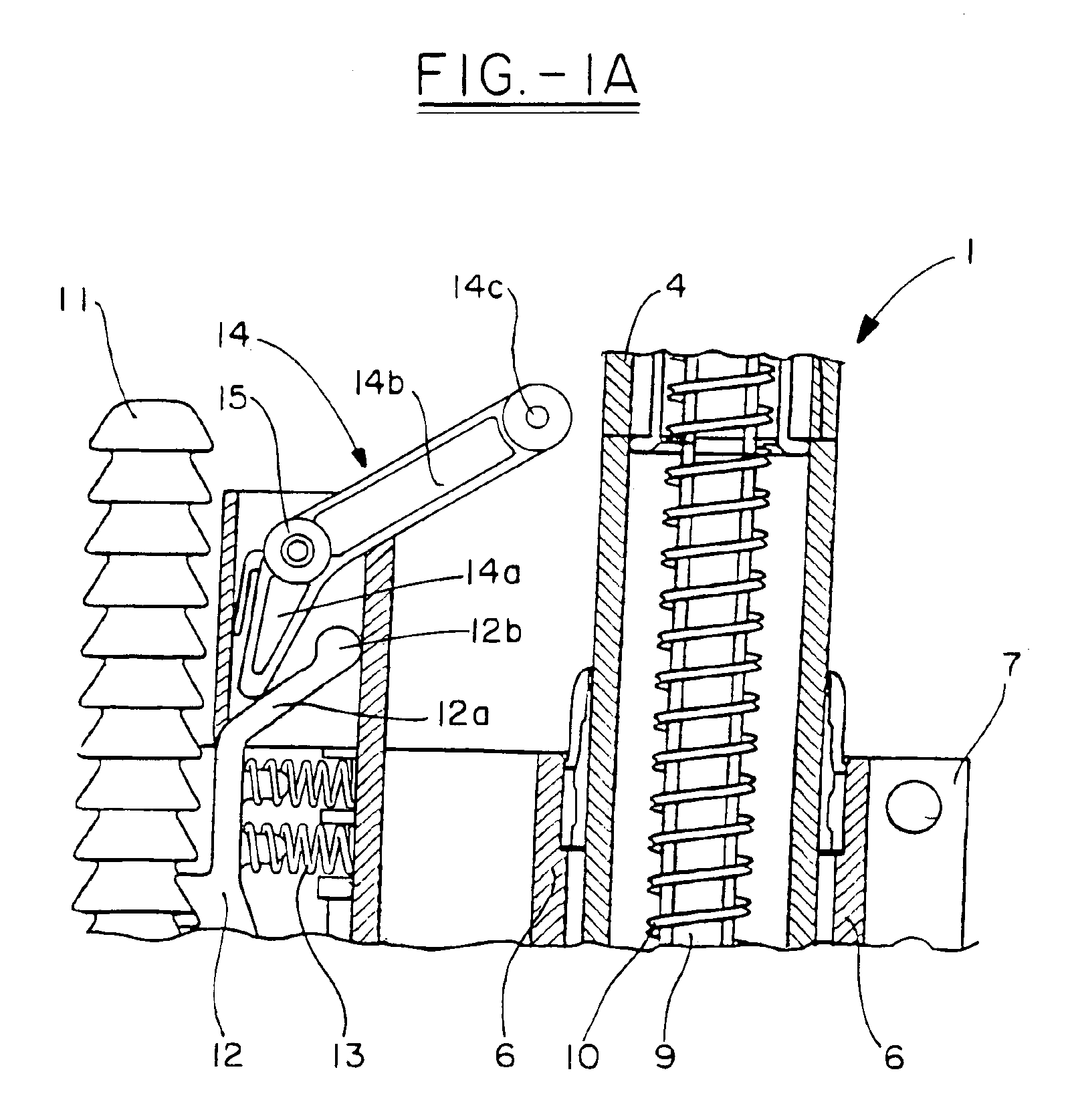
[0015]This measure according to the invention to bring the double-armed reversing lever to a stable position above dead center makes possible an effective self-holding unlocking action of the locking pawl by simple and thus cost-effective means.
[0019]To minimize the production costs for the locking pawl with its extension, a further embodiment provides that the extension of the locking pawl with its end stop is formed as an integral part of the locking pawl.
[0021]To ensure a supple operative engagement between the control surface and the actuating lever arm, the actuating lever arm of the reversing lever is provided with a roller at its free end. This allows the control surface to slide easily over the roller.

Problems solved by technology

In both of these solutions, the increased air resistance and driving noise as well as the effect on the appearance of the vehicle in the case of convertibles are perceived as drawbacks.
The problem is that the two processes must be carried out simultaneously, i.e. the operator has to use one hand to pivot the locking pawl and the other hand to push the rollover bar into the cassette.
This pushing-in requires substantial force to compress the strong compression drive springs.
This prior-art unlocking mechanism is very complex, however.

Method used


Image

  • Rollover protection system for motor vehicles with self-holding unlocking mechanism
  • Rollover protection system for motor vehicles with self-holding unlocking mechanism
  • Rollover protection system for motor vehicles with self-holding unlocking mechanism

Examples


Embodiment Construction

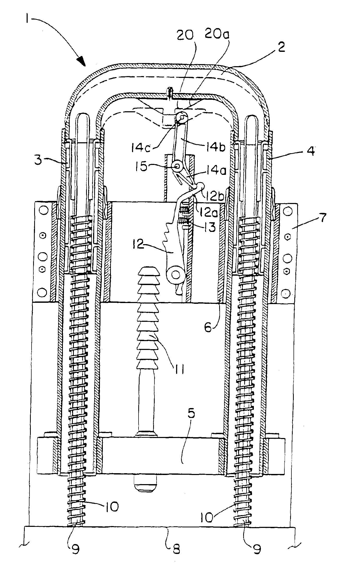
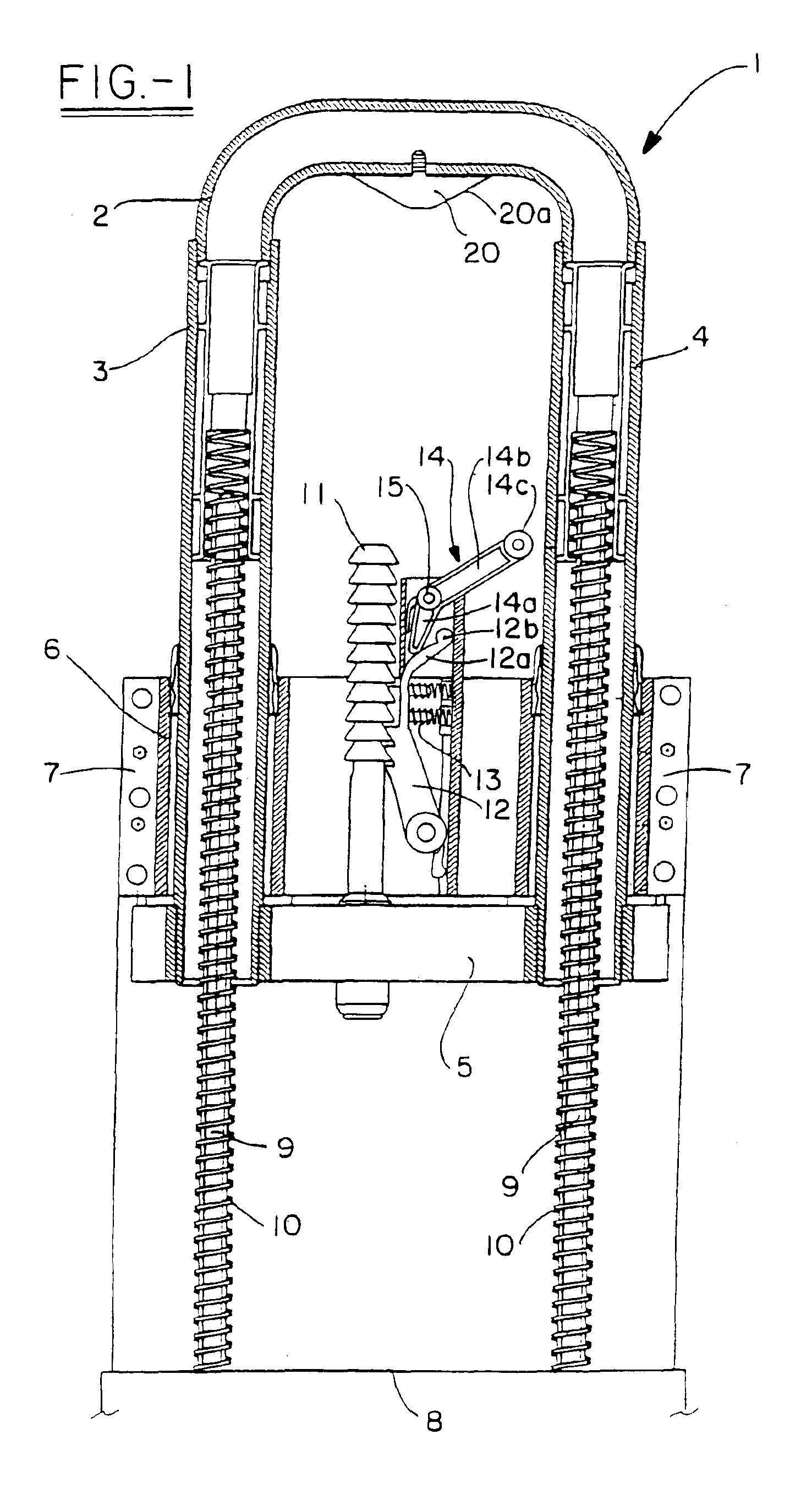
[0027]FIGS. 1 and 2 show an exemplary embodiment of the rollover bar system according to the invention with the rollover bar 1 depicted in its extended position in FIG. 1 and in its retracted position in FIG. 2.

[0028]The basic structure of the depicted rollover bar system according to the cassette principle is known, for instance, from the cited German Patent Specification DE 43 42 400 C2 and the associated further development in accordance with the German Laid Open Publication DE 43 42 400 A1.

[0029]The rollover bar is composed of three tubes, 2, 3, 4. The base of the rollover bar 1 is essentially formed by a curved tube 2, also referred to as the bar head, the ends of which are rigidly connected with two side tubes 3, 4 either by welding or by some other suitable joining process.

[0030]The ends of the side tubes 3, 4 are interconnected by a cross member 5.

[0031]The side tubes 3, 4 are mounted and guided in a guide block 6 of the cassette, which is fixed to the vehicle. The cross mem...


PUM


Abstract

Such systems typically have an extendable rollover bar, which in its extended position is locked against being pushed back in by a locking pawl that is in operative locking engagement with a toothed segment. To make it possible by simple means to use both hands to return the rollover bar to its retracted position when required, the invention provides a reversing lever, which can be manually brought to a self-holding position above dead center while unlocking the locking pawl before the rollover bar is pushed in. This self-holding position can be automatically canceled again just before the rollover bar reaches its standby position.

Description

FIELD OF THE INVENTION[0001]The invention relates to a rollover protection system for motor vehicles. It comprises a rollover bar, which is received and guided in a guide unit fixed to the vehicle and which in its normal state is held in a lower retracted standby position by a holding device against the force of at least one preloaded compression drive spring and with the release of the holding device can be brought into an upper protective locked position by the spring force of the compression drive spring. The system further comprises a locking mechanism for motor vehicles with a rollover bar which is received and guided in a guide unit fixed to the vehicle and which in its normal state is held in a lower, retracted standby position by a holding device against the force of at least one preloaded compression drive spring and with the release of the holding device can be brought into an upper protective locked position by the spring force of the compression drive spring. The system ...

Claims


Application Information

Patent Timeline
Patent Type & Authority Patents(United States)
IPC IPC(8): B60R21/13
CPCB60R21/13Y10T74/20648B60R2021/135
Inventor NASS, MICHAEL
Owner ISE INNOMOTIVE SYST EURO
Learn More