High performance valve assembly for toilets

a high-performance, valve-type technology, applied in the direction of water installation, flushing devices, construction, etc., can solve the problems of affecting the amount and quality of suitable water, unable to combine compliance with enhanced flushing and sanitary performance, and excessive consumption of potable water, etc., to overcome the deficiencies of conventional flushing valve assemblies, the effect of optimal energy and more available energy

Active Publication Date: 2005-06-07
AS IP HOLDCO LLC
View PDF6 Cites 22 Cited by
  • Summary
  • Abstract
  • Description
  • Claims
  • Application Information

AI Technical Summary

Benefits of technology

[0008]It is an advantage of the present invention to provide a flush valve assembly that overcomes the deficiencies of conventional flush valve assemblies.
[0009]It is also an advantage of the present invention to provide a flush valve assembly having optimal energy throughout of the flush water in comparison to existing flush valve assemblies to thereby provide more available energy for waste removal from the toilet bowl.
[0010]It is a further advantage of the present invention to provide a flush valve assembly that satisfies governmental agency requirements for a minimum “hold down” duration.
[0011]It is yet a further advantage of the present invention to provide a flush valve assembly that includes a “trip-release” mechanism to release the effect of the flush activation member (i.e., flush lever) upon closure of the valve opening so that a predetermined quantity of flush water is quickly delivered into the toilet bowl without exceeding mandated agency requirements.
[0012]It is still a further advantage of the present invention to provide a flush valve assembly having all of the aforementioned benefits in combination with noise reduction capabilities.
[0013]It is still another advantage of the present invention to provide a flush valve assembly having all of the aforementioned benefits in combination with reduced splashback of fluid in the toilet tank.

Problems solved by technology

The excessive consumption of potable water, however, remains a dilemma for water agencies, commercial building owners, homeowners, residents and sanitaryware manufacturers.
An increasing global population has negatively affected the amount and quality of suitable water.
Sanitaryware and flush valve manufacturers have attempted various techniques to comply with reduced water requirements and minimum “hold down” times. Such compliance has proven difficult to combine with enhanced flushing and sanitary performance.
Unfortunately, conventional flush valve configurations employ a coaxial flush valve assembly wherein the effective flow diameter through the flush valve opening is less than the orifice diameter of the flush valve inlet under dynamic conditions.
Such configurations therefore do not utilize the maximum available hydraulic energy.

Method used


Image

  • High performance valve assembly for toilets
  • High performance valve assembly for toilets
  • High performance valve assembly for toilets

Examples


Embodiment Construction

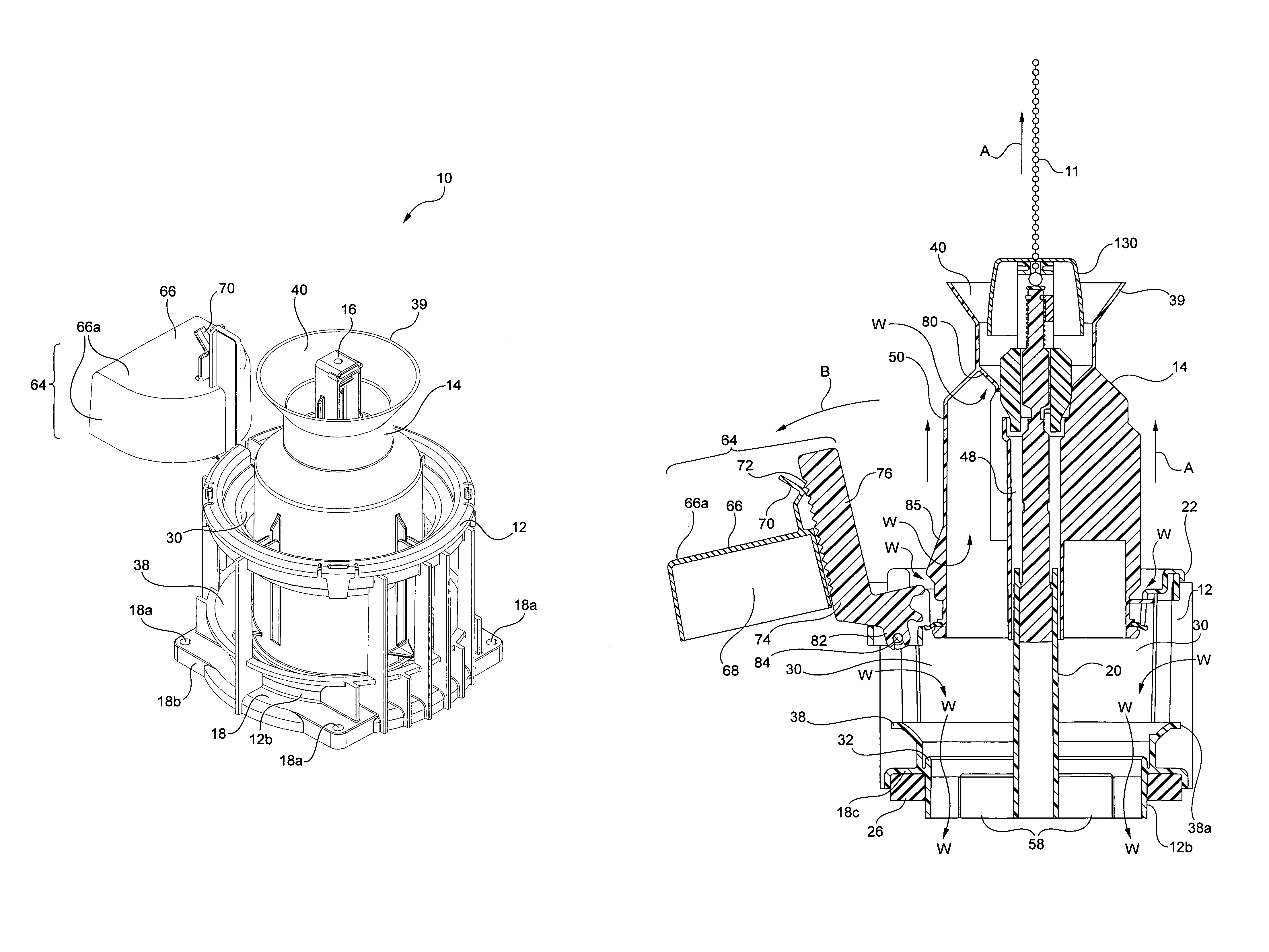
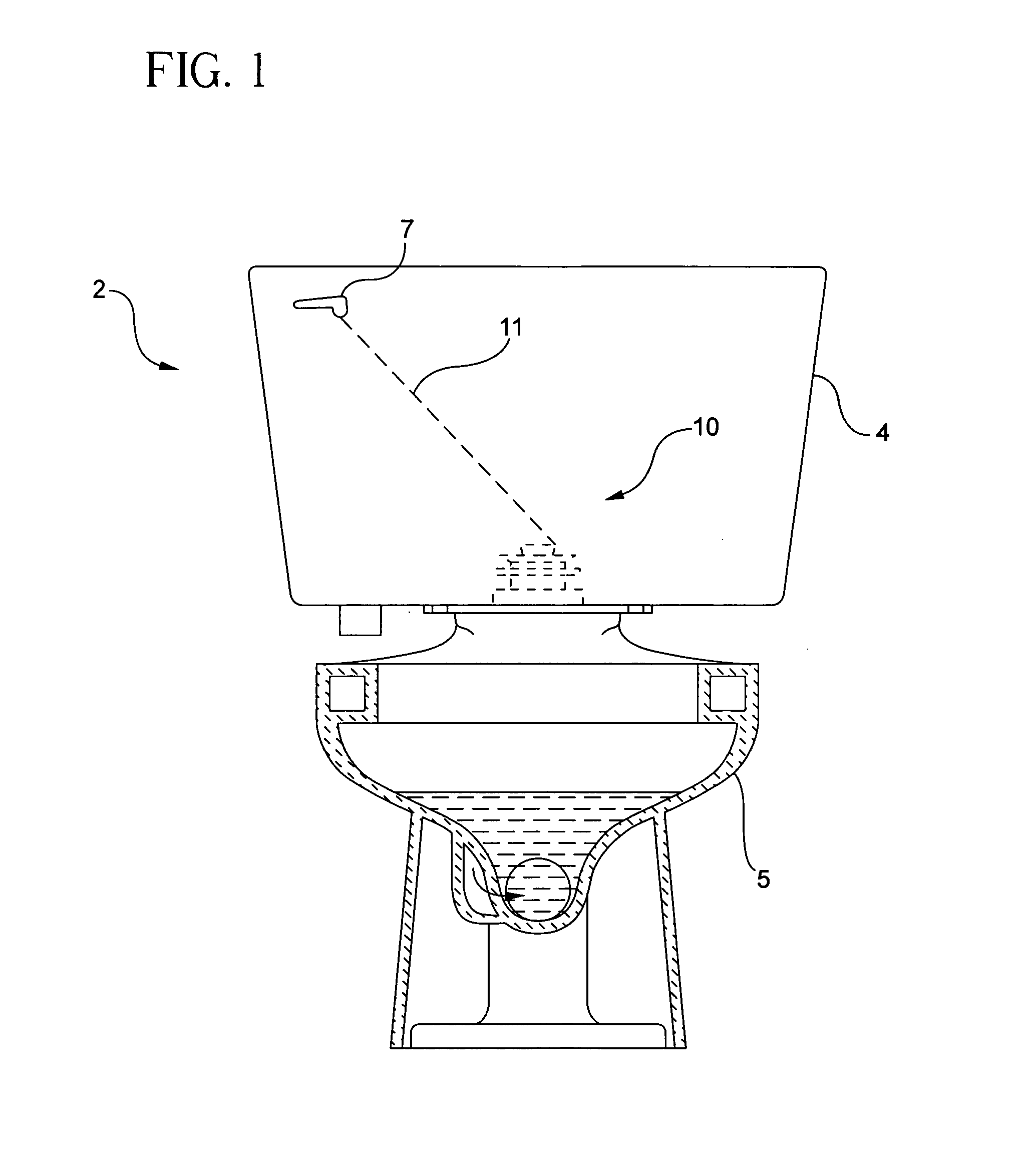
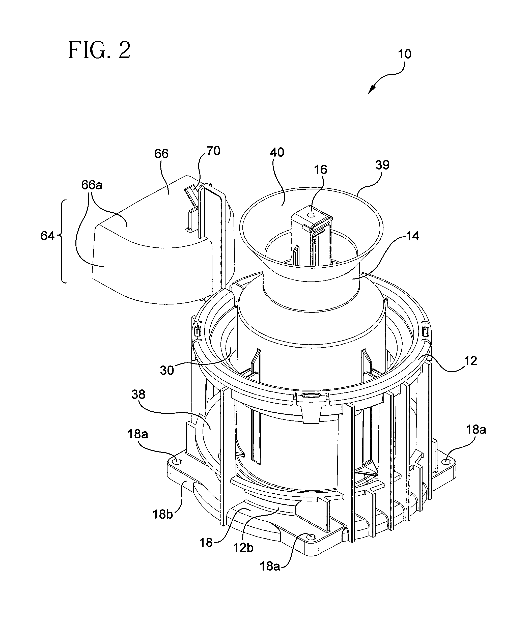
[0026]A flush valve assembly 10 in accordance with the teachings of the present invention is illustrated in FIG. 1 incorporated in a toilet assembly 2. As will be explained in more detail below, flush valve assembly 10, which is provided in a water tank 4, has a greater energy throughput of flush water in comparison to existing flush valves assemblies to thereby utilize maximum available energy to remove waste from toilet bowl 5. In addition, the present invention enables a toilet to meet regulatory mandates that require a minimum hold down time of 1 second and a maximum water usage of 1.6 gallons (6 liters) per flush. Flush valve assembly 10 allows water tank 4 to hold a predetermined volume of water and also supply a conduit to deliver reseal water to the toilet trapway via the passages within the toilet (this delivery is well known within the art). As illustrated in FIGS. 2 to 11, flush valve assembly 10 of the present invention includes valve body 12, flush cover member 14 of a ...


PUM


Abstract

A flush valve assembly includes a valve body with a first cylindrical tube member and a flush cover member that is coaxially and slidably mounted with respect to the valve body so as to create a valve opening therebetween when the flush cover member is removed from the valve body. A guiding means is provided that includes a second cylindrical tube member secured to the flush cover member and slidably fitted over the first cylindrical tube member. The guiding means further includes at least one alignment tab on the flush cover member that engages a corresponding tab recess defined in the valve body. A secondary float assembly pivotably affixed to the valve body has a flotation cup with a resilient member integral therewith. A pawl member includes retention members in combination with each of a primary finger and a secondary finger that engage an integral tab portion along an outside peripheral surface of the flush cover member during reciprocating movement of the flush cover member. A trip release mechanism that is coaxially mounted with respect to the valve body and flush cover member releases the effect of a flush lever on the flush cover member when the flush cover member reaches a position that permits fluid flow through the valve opening. A baffle cup is provided that has an outer periphery defining a float cavity therewithin and at least one aperture provided therethrough to establish communication among the flush lever, baffle cup and trip release means.

Description

FIELD OF THE INVENTION[0001]The present invention is directed to a flush valve assembly for use in a water tank of a toilet. More particularly, the present invention is directed to a flush valve assembly having a coaxial design that provides enhanced energy throughput and thereby optimizes the amount of available energy to effect waste removal from the toilet bowl. The valve assembly of the present invention consistently maximizes energy throughput by employing a large orifice diameter in combination with a trip release mechanism and a secondary float assembly pivotably affixed to a valve body. The flush valve of the present invention also includes shock-absorbing structure for quiet closure of the valve opening and a baffle cup that reduces splashing within the tank.BACKGROUND OF THE INVENTION[0002]Toilets for removing waste products are well known. Typically, toilets incorporate three systems that work together to perform the flushing action: the bowl siphon, the flush mechanism a...

Claims


Application Information

Patent Timeline
Patent Type & Authority Patents(United States)
IPC IPC(8): E03D1/34E03D1/30
CPCE03D1/34
Inventor JENSEN, ROBERTHAN, JOSEPH UNKYUNG
Owner AS IP HOLDCO LLC
Why Eureka
Try Eureka