
Method and apparatus for blocking effect reduction

Inactive Publication Date: 2005-05-24
AMBERFIN
View PDF37 Cites 184 Cited by
  • Summary
  • Abstract
  • Description
  • Claims
  • Application Information

AI Technical Summary

Benefits of technology

[0001]This invention relates to the estimation of the subjective quality of a picture that has been decode

Problems solved by technology

A problem to be solved is that of estimating the subjective picture quality of a picture or sequence decoded from an MPEG-2 bitstream.

Method used


Image

  • Method and apparatus for blocking effect reduction
  • Method and apparatus for blocking effect reduction
  • Method and apparatus for blocking effect reduction

Examples


Embodiment Construction

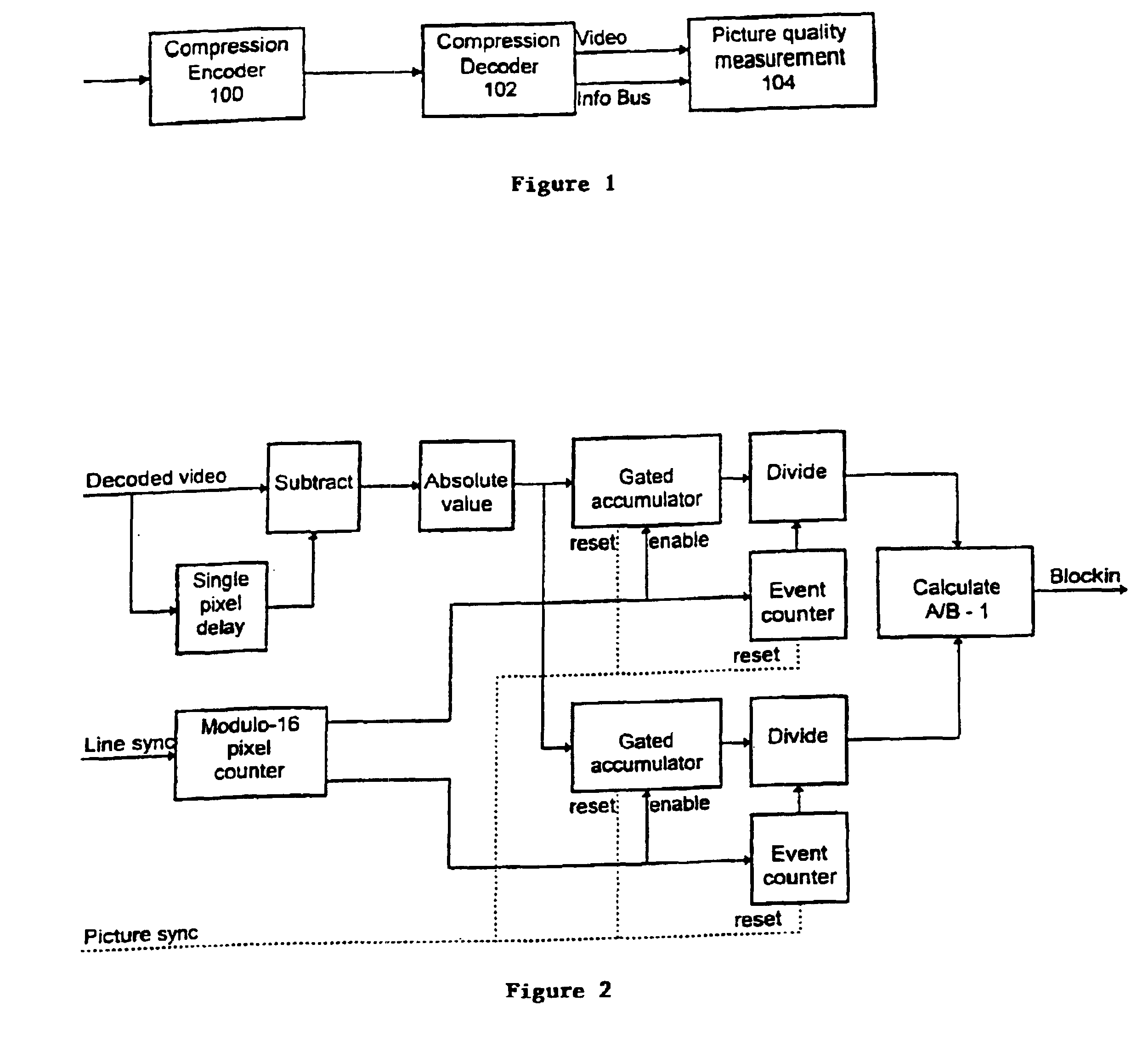
[0019]The basic architecture of single-ended quality measurement is shown in FIG. 1.

[0020]The MPEG signal from a remote, upstream encoder 100 is received by a decoder 102 which is adapted as described in the previously mentioned references to provide an Information Bus output, in addition to the decoded video. The picture quality measurement unit 104 therefore has access not only to the decoded video but also to coding decisions which were taken by the encoder 100 and which are of course implicit in the MPEG bit-stream.

[0021]The picture quality measurement process in one embodiment operates only from information available at the decoder side of the compression codec; the decoded video signal and the Information Bus containing the coding decisions and parameters. It has no access to the picture source. Because of this, the quality measurement can never be completely reliable because there is no way of telling which degradations in the picture are due to the current coding process and...


PUM


Abstract

By utilizing parameters derivable from a compressed bit-stream, measures are obtained of the subjective quality of a decoded picture, without the necessity for reference to source material. A blockiness measure is derived both locally and globally and used to control a de-blocking filter. An estimate of signal-to-noise ratio is derived from quantization values.

Description

SUMMARY OF THE INVENTION[0001]This invention relates to the estimation of the subjective quality of a picture that has been decoded from a compressed bit-stream and in certain aspects to techniques for improving that subjective quality.[0002]Generally, both the bitstream itself and the decoded picture will be accessible but the original source will not; hence the term ‘single-ended’ will be applied. Such a single-ended estimate will clearly not be as reliable as one in which the source picture can be compared to the decoded output, but it can serve as a useful indicator of potential problems in a broadcast chain involving compression when the bitstream is being monitored.[0003]The invention relates in the most important example to the MPEG-2 video compression standard, but applies more broadly to transform based compression systems.[0004]A problem to be solved is that of estimating the subjective picture quality of a picture or sequence decoded from an MPEG-2 bitstream. The usual me...

Claims


Application Information

Patent Timeline
IPC IPC(8): H04N7/26H04N7/30H04N17/00G06T5/20
CPCH04N17/004H04N19/176H04N19/172H04N19/60H04N19/117H04N19/59H04N19/154H04N19/80H04N19/527H04N19/86H04N19/136
Inventor KNEE, MICHAEL JAMESDIGGINS, JONATHAN
Owner AMBERFIN
Learn More