
Fair bandwidth sharing for video traffic sources using distributed feedback control

Inactive Publication Date: 2005-05-17
AMERICAN TELEPHONE & TELEGRAPH CO
View PDF30 Cites 44 Cited by
  • Summary
  • Abstract
  • Description
  • Claims
  • Application Information

AI Technical Summary

Benefits of technology

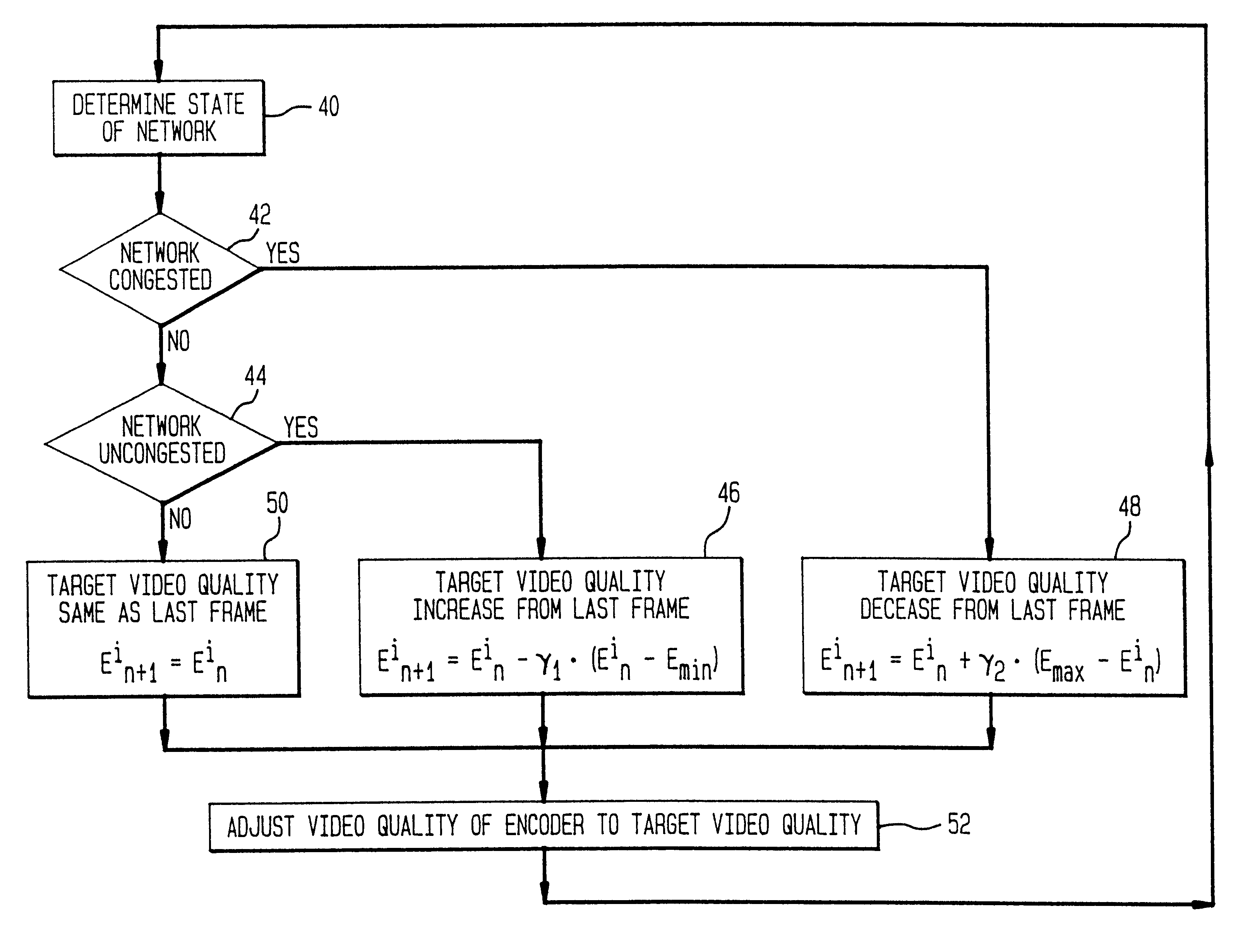
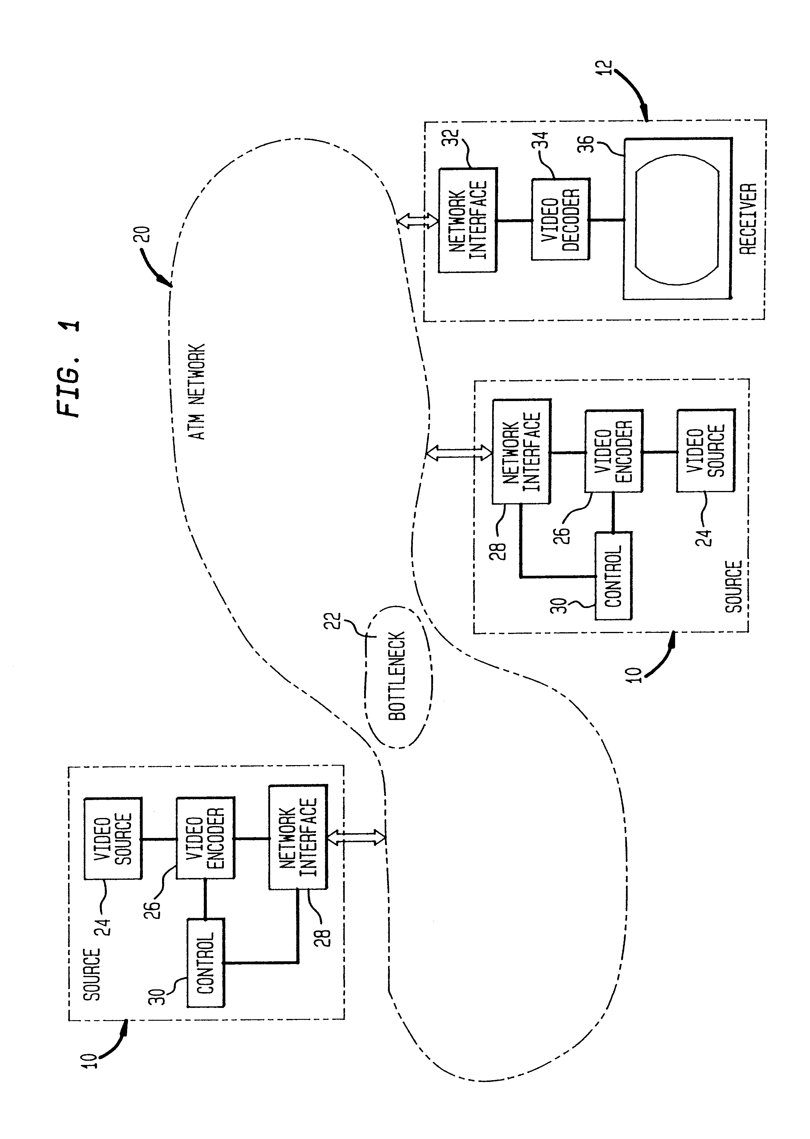
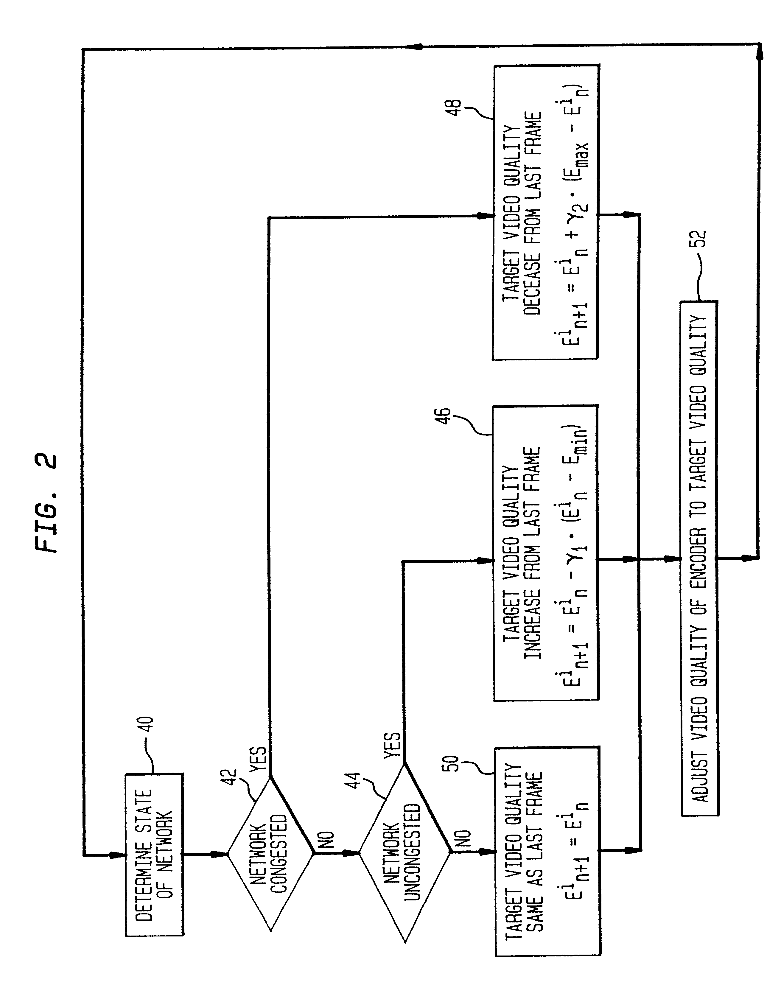
[0007]In accordance with the present invention, an apparatus and a method provides fair bandwidth sharing by adjusting video image quality in a data packet network. The present invention comprises a network load detection means for detecting a network load and a video encoding control circuit. The network load has an uncongested state, a loaded state, and a congested state. The video encoding control circuit adjusts a video quality to a target video quality, by increasing the video quality when the network load is in the uncongested state and decreasing the video quality when the network load is in the congested state.

Problems solved by technology

However, a major problem exhibited by these earlier schemes is unfairness in the service provided to users—where the grade of service is defined in terms of the quality of the video signal delivered to the user.
However, network overloads can cause data loss due to buffer overflows or excessive delays with a consequent degradation in image quality.
However, a drawback is that during periods of overload, sources with more complex image sequences see a greater reduction in image quality.
A divergence in image quality of more than 5 dB between sources has been observed, resulting in clearly visible differences in the picture quality.
This unfairness occurs because while more complex image sequences require a greater amount of bandwidth to obtain the same level of quality, the feedback control schemes attempt to achieve parity in the bandwidth used by each source.

Method used


Image

  • Fair bandwidth sharing for video traffic sources using distributed feedback control
  • Fair bandwidth sharing for video traffic sources using distributed feedback control
  • Fair bandwidth sharing for video traffic sources using distributed feedback control

Examples


Embodiment Construction

[0031]Although the present invention, an apparatus for fair bandwidth sharing in a data packet network is particularly well suited for use with an ATM network, and shall be described with respect to this application, the methods and apparatus disclosed here can be applied to other packet video networks as well.

[0032]The present invention is an apparatus for adjusting video image quality in a data packet network to provide Fair Bandwidth Sharing by adaptation of the quantization source rate of video encoders. This achieves fairness by using the image quality as the primary variable for modulation of encoder behavior in response to feedback signals from the network. The network feedback information used consists of a single bit of information about the aggregate load at the bottleneck link.

[0033]Feedback from the network is used to determine a target image quality; the video encoder then tries to match this target quality by adjusting the quantizer step size. The system used for deter...


PUM


Abstract

An apparatus and a smethod providing fair bandwidth sharing by adjusting video image quality in a data packet network comprises a network load detection means for detecting a network load and a video encoding control circuit. The network load has an uncongested state, a loaded state, and a congested state. The video encoding control circuit adjusts a video quality to a target video quality, by increasing the video quality when the network load is in the uncongested state and decreasing the video quality when the network load is in the congested state. The video quality is determined as a peak mean squared error between an uncompressed image and a corresponding decoded image. The network load is detected by using a forward explicit congestion notification bit.

Description

[0001]This is a division of co-pending application Ser. No. 09 / 561,337, filed on Apr. 28, 2000 now U.S. Pat. No. 6,456,591, which in turn is a continuation of application Ser. No. 08 / 555,534, filed on Nov. 9, 1995, now U.S. Pat. No. 6,075,768.FIELD OF THE INVENTION[0002]This invention relates to systems for transmission and reception of digital video over packet switched networks, and more particularly to video signal encoding responsive to network feedback.BACKGROUND OF THE INVENTION[0003]In earlier work it has been shown that a promising approach for transporting real-time video traffic in packet switching networks is to use feedback from the network to modulate the source rate of a video encoder. However, a major problem exhibited by these earlier schemes is unfairness in the service provided to users—where the grade of service is defined in terms of the quality of the video signal delivered to the user.[0004]Two distinct approaches are currently utilized for supporting real-time...

Claims


Application Information

Patent Timeline
IPC IPC(8): G01R31/08G06F11/00G08C15/00H04J1/16
CPCH04L47/10H04L47/38H04L47/33H04L47/11
Inventor MISHRA, PARTHO PRATIM
Owner AMERICAN TELEPHONE & TELEGRAPH CO
Learn More