
Pneumatic particulate dispensing system

a technology of pneumatic particulate and dispensing system, which is applied in the direction of liquid handling, potato planters, packaging goods types, etc., can solve the problems of difficult assembly or transportation of known particulate dispensers, complex and expensive devices used in blower units, etc., to achieve easy and efficient manufacturing and marketing, low manufacturing cost, and low price of sale

Inactive Publication Date: 2005-05-17
HEBERT SHELTON L +1
View PDF17 Cites 47 Cited by
  • Summary
  • Abstract
  • Description
  • Claims
  • Application Information

AI Technical Summary

Benefits of technology

[0024]It is another object of the present invention to provide a new and improved pneumatic particulate dispensing system that may be easily and efficiently manufactured and marketed.
[0025]An even further object of the present invention is to provide a new and improved pneumatic particulate dispensing system that has a low cost of manufacture with regard to both materials and labor, and which accordingly is then susceptible of low prices of sale to the consuming public, thereby making such pneumatic particulate dispensing system economically available to the buying public.
[0027]Even still another object of the present invention is to provide a pneumatic particulate dispensing system for dispensing particulate material through a portable pneumatic device. This allows a user with an easy and lightweight system for adjustably dispensing particulate material over a large surface or into an overhead receptacle. The system can be used by a single hunter, for example, for filling overhead animal feeders. The off the shelf components allows the pneumatic particulate dispensing system to be easily assembled and transported to any desired located by mounting the system on a support frame which is adapted to be inserted into a standard vehicle hitch.

Problems solved by technology

In current particulate dispensers, dispensing of particulate material is performed using complex and expensive devices using blower units, hoppers, and discharge tubes.
Such devices use complex valve assemblies to adjust the flow of particulate material from the hopper to the passing airflow from the blower unit.
Furthermore, these known particulate dispensers are not easily assembled or transported, which adds to the time required by the user to assemble, transport, use, and disassemble the dispensing device.
This method is inherently dangerous to the hunter, as well as strenuous and time consuming.
While each of these systems may provide devices for dispensing material, they do not teach the use of a portable device for pneumatically dispensing particulate material fed by a hopper through a rotatable gate valve connected to a T-fitting which encloses a velocity tube.
While the above-described devices fulfill their respective, particular objectives and requirements, the aforementioned patents do not describe a pneumatic particulate dispensing system having an air blower connected to a velocity tube via an adapter, which allows for the use of a variety of different air blowers, wherein the velocity tube creates a vacuum that removes the particulate material from an above mounted hopper through an adjustable rotary valve.
Furthermore, the above-described devices make no provisions for a rotary valve that is connected to a T-fitting which encloses the velocity tube, wherein the rotary valve extends into the hopper, and whereby the entire system is supported by cradles mounted to a support frame adapted to inserted into a vehicle trailer hitch.

Method used


Image

  • Pneumatic particulate dispensing system
  • Pneumatic particulate dispensing system
  • Pneumatic particulate dispensing system

Examples


Embodiment Construction

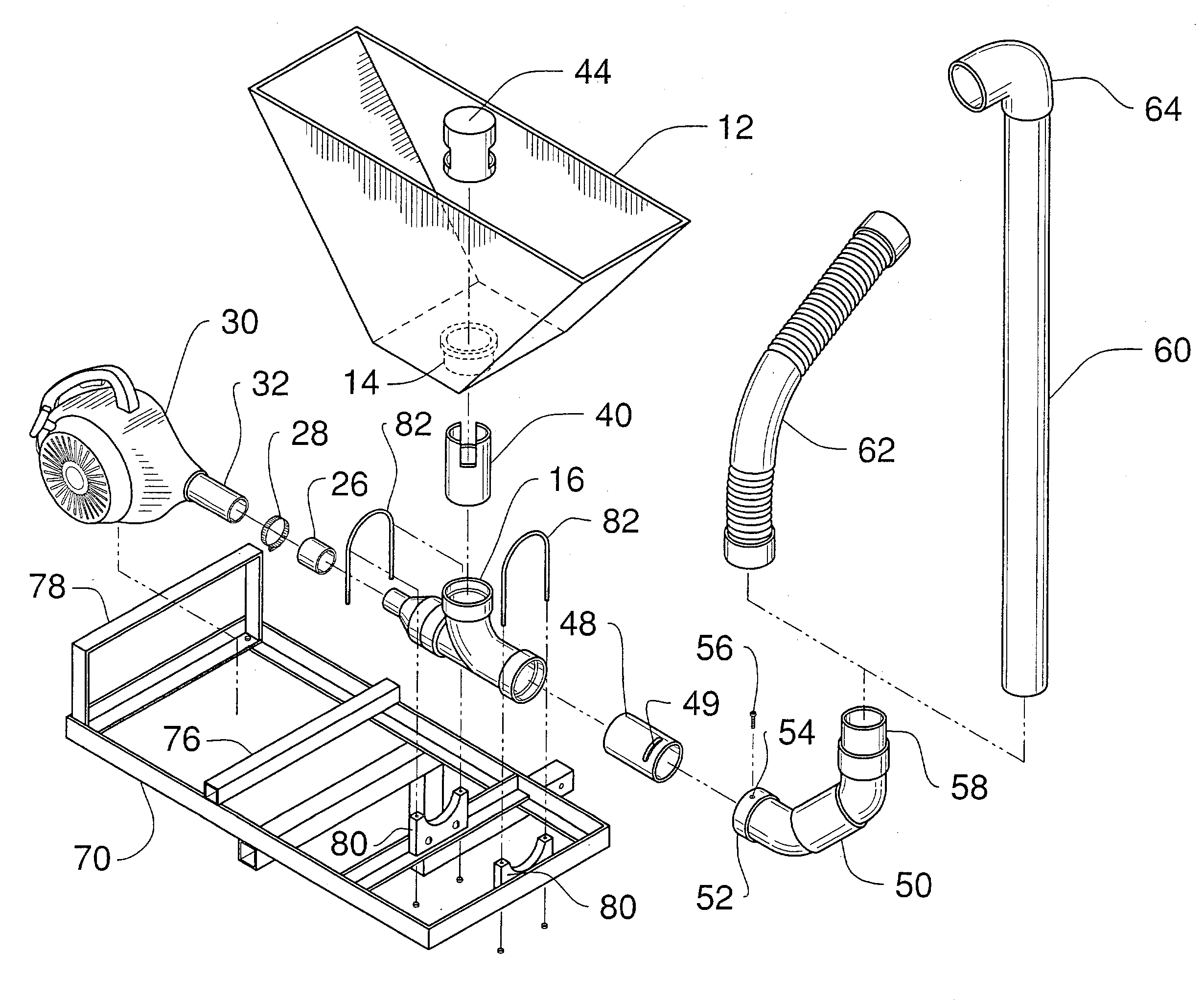
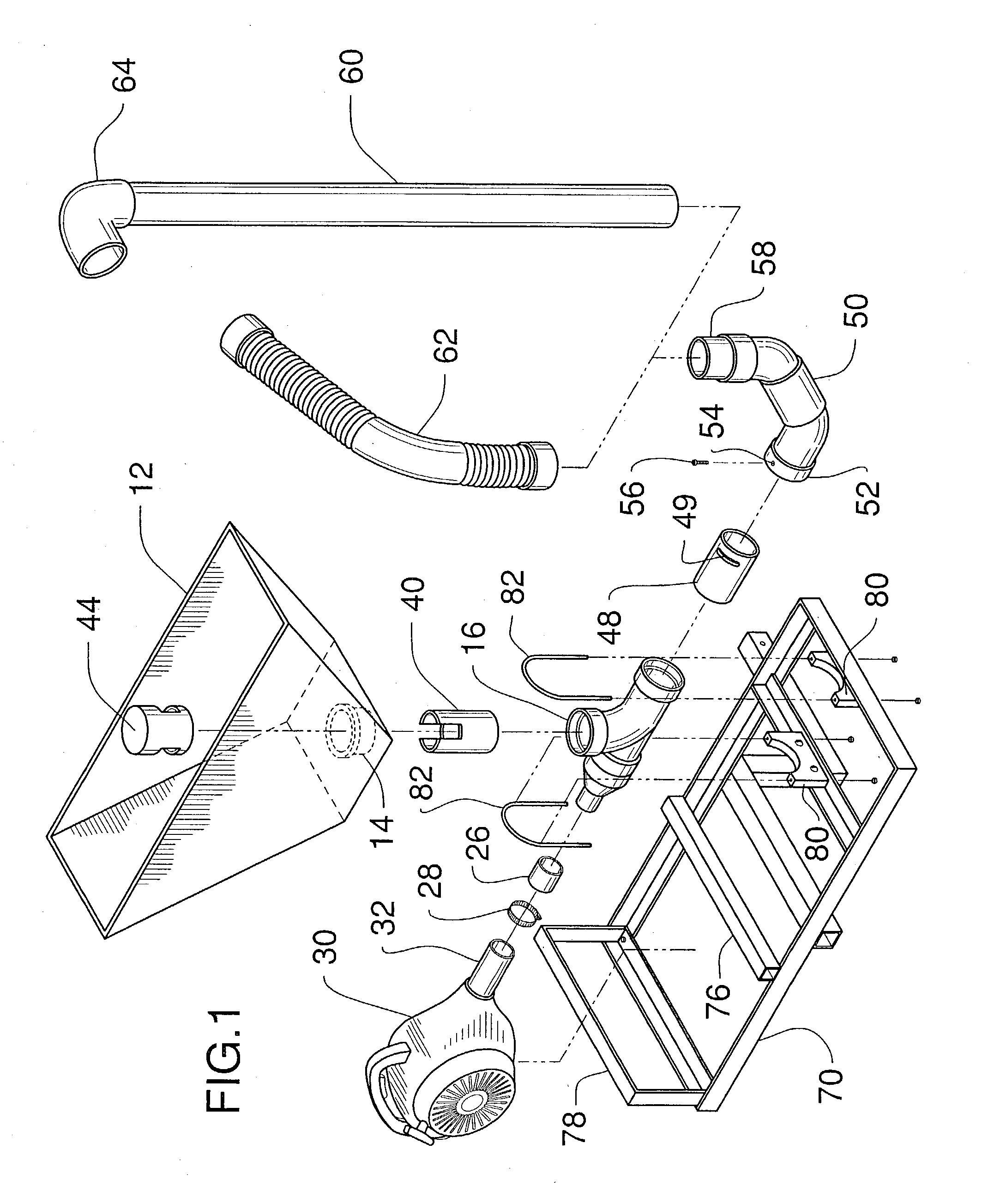
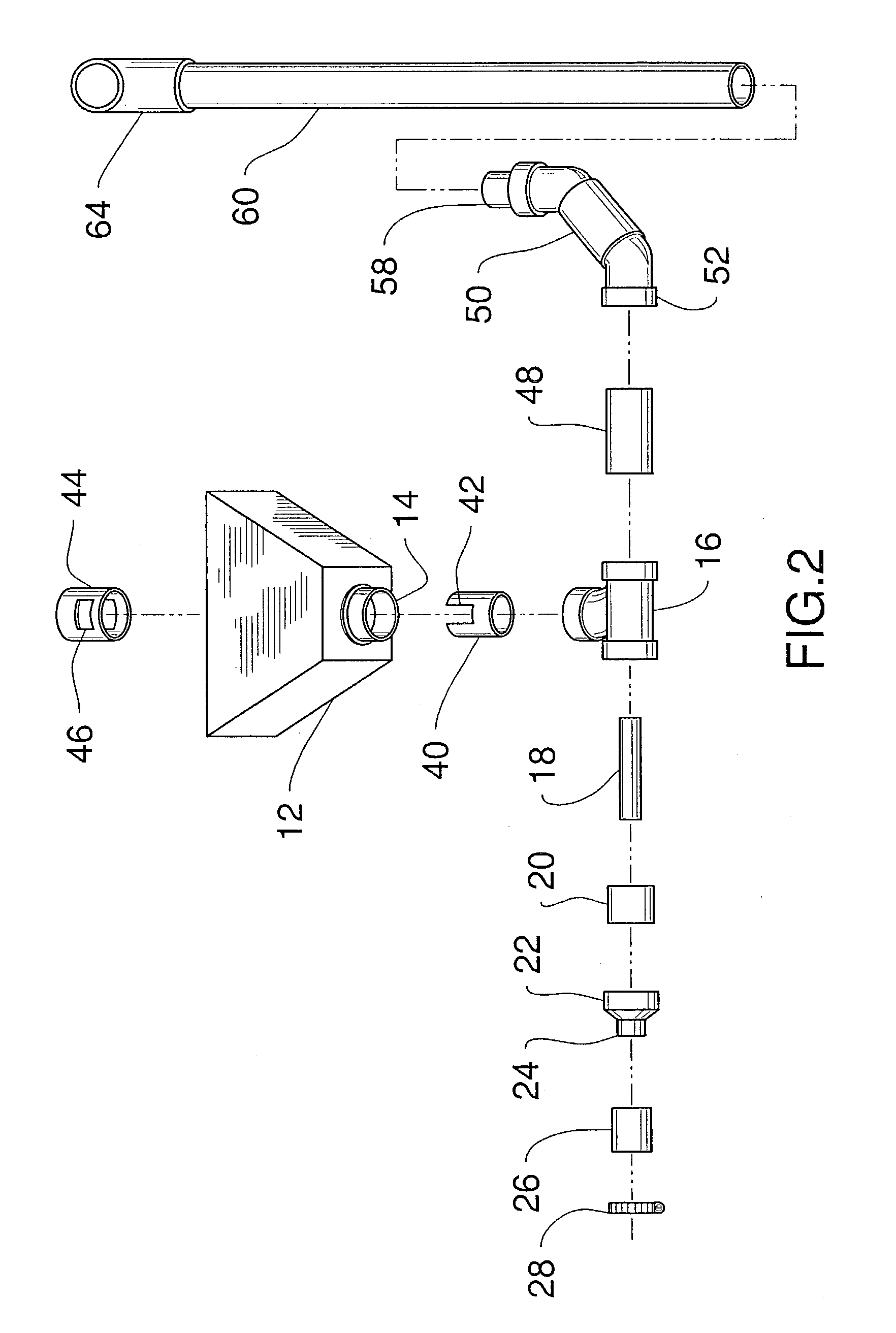
[0038]Referring now to the drawings, and particularly to FIGS. 1–6, a preferred embodiment of the pneumatic particulate dispensing system of the present invention is shown and generally designated by the reference numeral 10.

[0039]In FIG. 1, a new and improved pneumatic particulate dispensing system 10 of the present invention for pneumatically dispensing particulate material is illustrated and will be described. More particularly, the pneumatic particulate dispensing system 10 has a hopper 12 mounted to a top oriented opening of a T-fitting 16 by a flanged adapter 14. The T-fitting 16 is hollow, allowing for fluid to travel therethrough. The hopper 12 is adapted to receive and retain particulate material such as, but not limited to, corn, protein, food, fertilizers, seeds, pesticides, herbicides and insecticides. The T-fitting 16 is connected to a reducer 22 and to a discharge tube 48, thereby coupling the hopper 12, the reducer 22, and the discharge tube 48 in fluid communication ...


PUM

PropertyMeasurementUnit
Velocityaaaaaaaaaa

Abstract

A pneumatic particulate dispensing system having a hopper for storing particulate material, such as animal feed, fertilizers, pesticides and the like. The hopper is connected to a T-fitting which encloses a velocity tube. An air blowing unit is connected to the T-fitting and the velocity tube through an interchangeable adaptor allowing for a variety of air blowing units to be installed. An adjustable rotary valve extends into the interior of the hopper from the T-fitting allowing for a user to adjust the amount of particulate material to be dispensed adjacent the velocity tube. A discharge tube is connected to the T-fitting downstream of the velocity tube, wherein the discharge tube has a rotating elbow for allowing the user to adjust the dispensing direction. A variety of nozzles can be attached to the end of the discharge tube. A support frame having a hitch insert and cradles is used to support and transport the particulate dispensing system to remote locations.

Description

BACKGROUND OF THE INVENTION[0001]1. Field of the Invention[0002]The present invention relates to a pneumatic particulate dispensing system for use in connection with the pneumatically dispensing of particulate material, such as fertilizers, seeds, pesticides, herbicides and insecticides. The pneumatic particulate dispensing system has particular utility in connection with providing a portable device for pneumatically dispensing particulate material.[0003]2. Description of the Prior Art[0004]Pneumatic particulate dispensing systems are desirable for distributing particulate material, such as corn, protein, food, fertilizers, seeds, pesticides, herbicides and insecticides through a singe portable device which can be easily mounted to a frame hitchably attachable to a vehicle. In current particulate dispensers, dispensing of particulate material is performed using complex and expensive devices using blower units, hoppers, and discharge tubes. Such devices use complex valve assemblies t...

Claims


Application Information

Patent Timeline
IPC IPC(8): A01C7/08A01C15/04B65G53/04B65G53/14
CPCA01C7/081B65G53/14A01C15/04A01C7/082
Inventor HEBERT, SHELTON L.DOERR, RUSSELL
Owner HEBERT SHELTON L
Learn More