
Variable sound-emitting toy for a pet

a sound-emitting toy and pet technology, applied in the field of pet toys, can solve the problems of endangering the health or safety of the animal, limiting the free play of toys, damage or destruction of toys, etc., and achieve the effect of increasing the likelihood of sound occurren

Inactive Publication Date: 2005-05-17
NGEN NEW GENERATION INNOVATIONS
View PDF6 Cites 55 Cited by
  • Summary
  • Abstract
  • Description
  • Claims
  • Application Information

AI Technical Summary

Benefits of technology

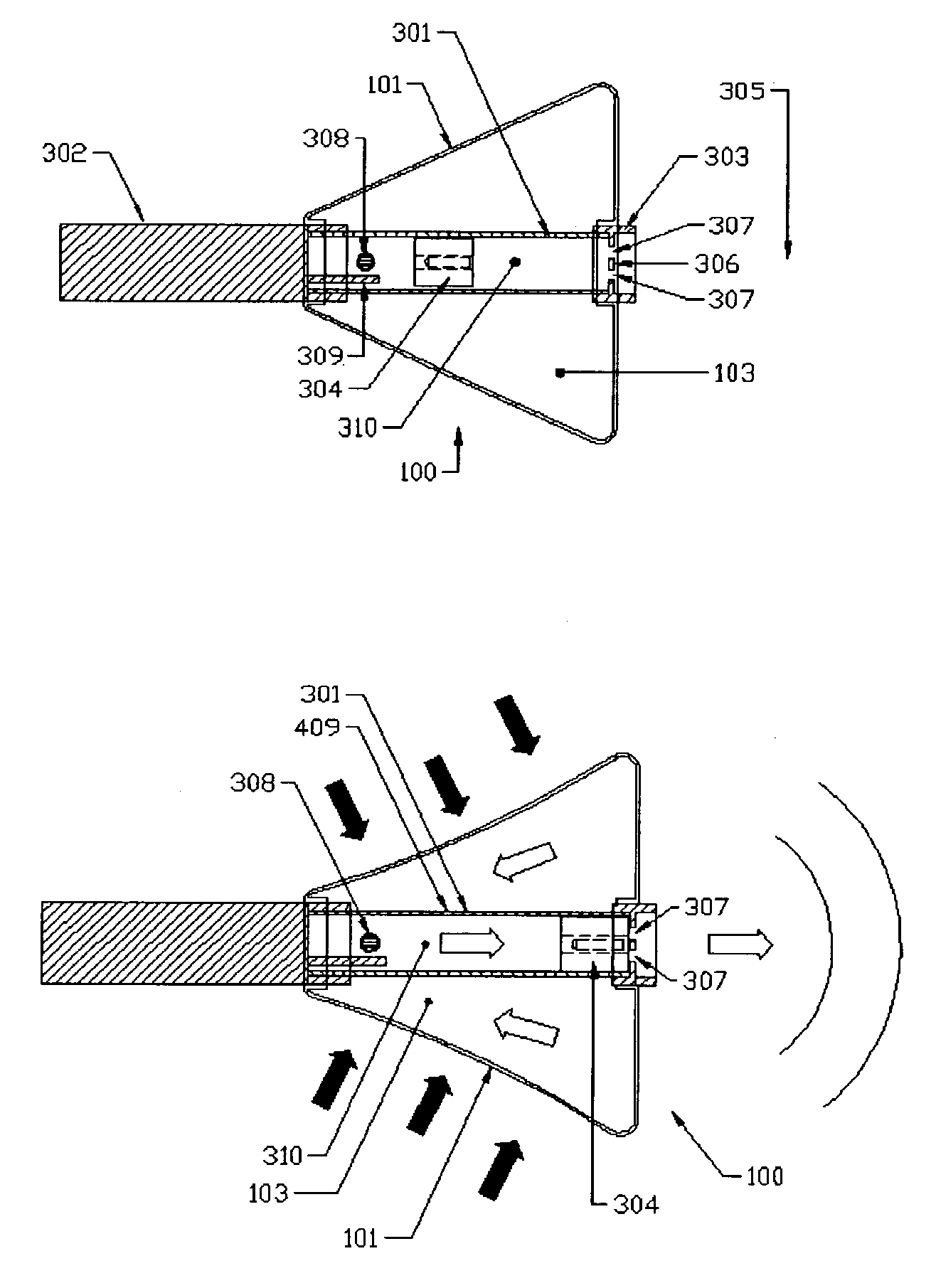
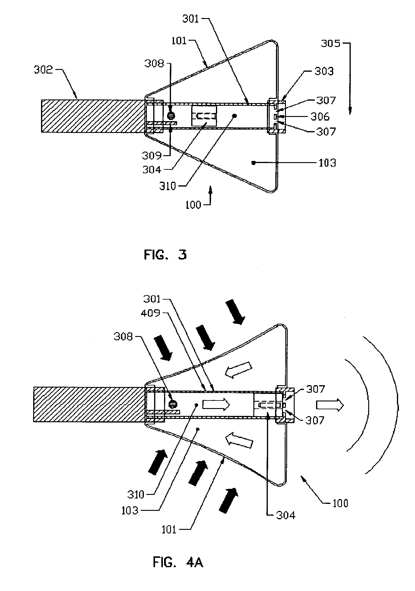
[0014]These methods of mechanical sound formation increase the likelihood of sound occurrence, regardless of the manner in which the toy is handled. For example, the physical compression or expansive decompression of the toy body portion and the movement of the sliding whistle component, which is moved by gravity or by centrifugal force, ensures that sound will be produced upon virtually any active handling of the toy.

Problems solved by technology

Furthermore, the prior art requires these toys to be altogether constructed of fabricated materials of an inflexible nature (i.e. rigid PVC plastic) to carry the sound tube device(s), thus inhibiting free play therewith.
In addition, toys of the prior art generally require direct supervision; as for pet usage, the animal's likely desire to chew will result in damage or destruction of the toy and endanger the health or safety of the animal.
The result is that the toy will only emit substantial amounts of sound if it is purposefully rotated on its axis to create a sound.
Such limited stimulation reduces the likelihood that a user, such as a pet, will be sufficiently interested in the toy to use as intended.
The result is that the ball will only emit substantial amounts of sound if it is handled purposefully in said manner so as to create the sound.

Method used


Image

  • Variable sound-emitting toy for a pet
  • Variable sound-emitting toy for a pet
  • Variable sound-emitting toy for a pet

Examples


Embodiment Construction

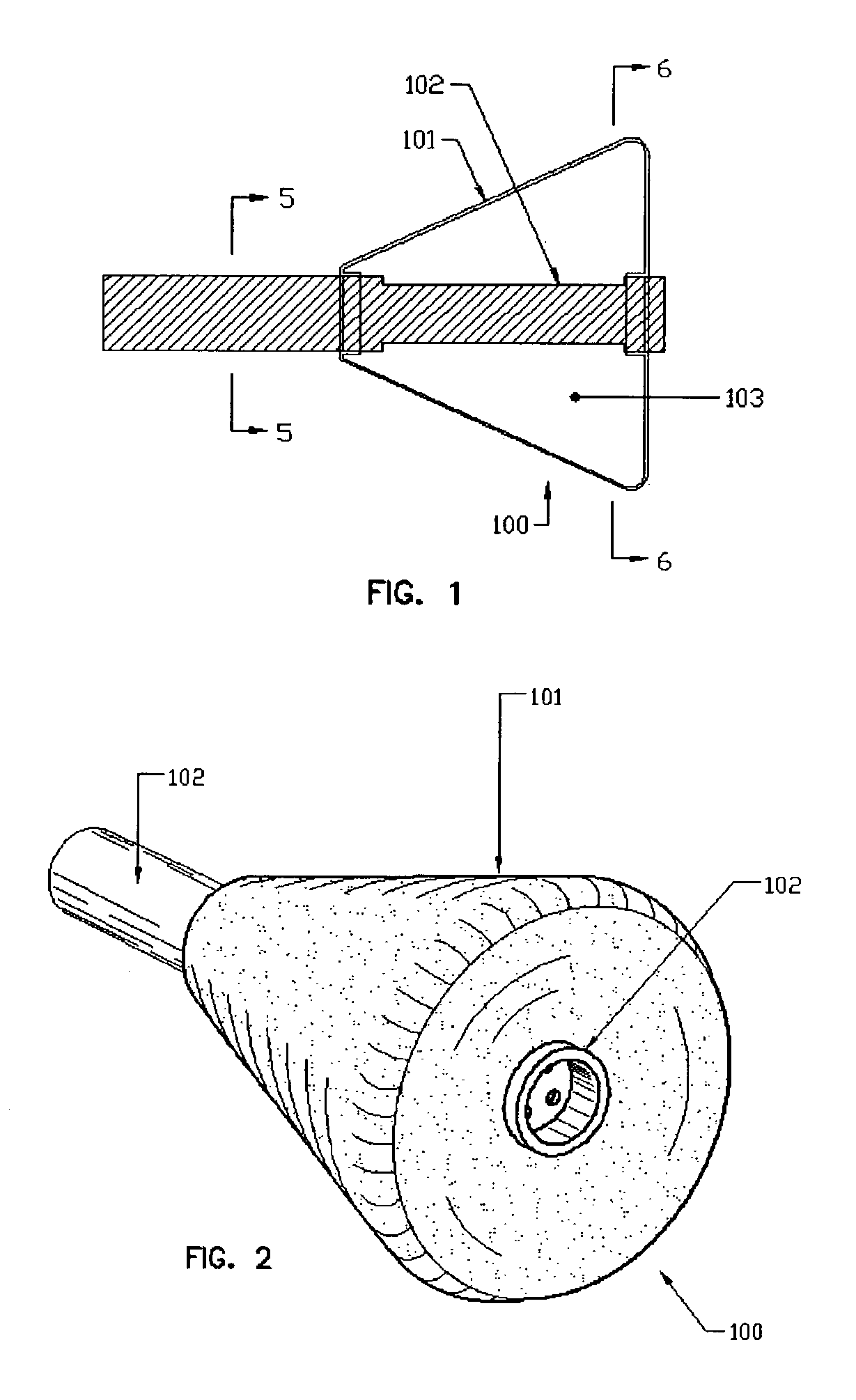
[0030]Referring now to the drawings, FIG. 1 is a partial sectional side view of a variable sound-emitting toy 100 according to aspects of the present invention, which is suitable for use in producing desired sound effects when manipulated by a user, such as a pet. As shown in FIG. 1, the toy body portion 101 preferably is (although not necessarily) comprised of a hollow three-dimensional form having a generally trapezoidal shape and having an interior space 103. Toy body portion 101 is preferably made from an elastomeric material and advantageously molded to approximately 3 mm in thickness and to a hardness in the range of 90 or less, preferably 30 to 50, most preferably 40 Shore A hardness (Scale Shore A).

[0031]As can be appreciated from FIG. 1, toy 100 includes a cylindrical frame 102 that is constructed and assembled of a rigid or semi rigid elastomeric or polymeric material, such as nylon, to support the hollow and elastomeric toy body portion 101. In the preferred embodiment of...


PUM


Abstract

This invention features a toy, which emits variable sounds generated by singular and / or collective methods, comprising of an assemblage of a first material forming article body portion, hereinafter named as “toy body portion,” comprised of substantially elastomeric materials and formed hollow, and a second material forming article frame portion, hereinafter known as “cylindrical frame” comprised of substantially rigid materials. Said cylindrical frame further comprises an integrated sound tube device with associated sliding whistle component. An air aperture is formed within the tubular wall of said sound tube and positioned so as enveloped by the interior cavity of the toy body portion, whereby physical compression or expansive decompression of the toy body portion will directionally actuate air into and through said sound tube device. In its preferred embodiment, said toy body portion has said cylindrical frame located centrally through toy body portion and protruding through each side thereof.

Description

BACKGROUND OF INVENTION[0001]This invention generally relates to a pet toy. In particular, this invention relates to a variable sound-emitting toy for a pet, that when manipulated by a user will produce and emit variable sounds by singular and / or collective methods.[0002]There are a number of non-electronic variable sound-emitting toys in the prior art for entertaining and stimulating their users with sound, often pets or children. The history of non-electronic, variable sound-emitting toys has generally involved solutions, which require both the purposeful rotation of the toy and gravity to emit sound through the conventional use of one or more mechanical sound tube devices. Furthermore, the prior art requires these toys to be altogether constructed of fabricated materials of an inflexible nature (i.e. rigid PVC plastic) to carry the sound tube device(s), thus inhibiting free play therewith. In addition, toys of the prior art generally require direct supervision; as for pet usage, ...

Claims


Application Information

Patent Timeline
IPC IPC(8): A01K15/02A01K15/00A63H5/00A01K11/00G10K5/00
CPCA01K15/026G10K5/00A63H5/00
Inventor DUBININS, DMITRIJS V.JELLICO, KENNETH A.
Owner NGEN NEW GENERATION INNOVATIONS
Learn More