Constant-current, rail-voltage regulated charging electronic detonator

a technology of electronic detonators and constant current, which is applied in the direction of electric fuzes, lighting and heating apparatuses, ammunition fuzes, etc. it can solve the problems of sagging of the bus, safety concerns, and the detonator has no current regulation, so as to simplify diagnostics and monitoring, prevent excessive current

Inactive Publication Date: 2005-05-17
AUSTIN STAR DETONATOR
View PDF13 Cites 18 Cited by
  • Summary
  • Abstract
  • Description
  • Claims
  • Application Information

AI Technical Summary

Benefits of technology

[0003]The present invention comprises the regulated charging of an energy storage module in a pyrotechnic device such as a firing capacitor in an electronic detonator. The regulation may preferably be in the form of constant-current charging limited at a “rail voltage,” wherein the amount of constant current is selected so that the charging time is adequately quick but is low enough to preclude any problems associated with a higher current draw, such as sagging of a bus and / or excessive surge into capacitors. For example, in an electronic blasting system, a constant current module in the electronic detonator may activate in response to receiving an appropriate command from the blasting machine during the arming stage. In a separate and independent aspect of the invention, it is possible that the constant current limit may be selected to be sufficiently low as to provide additional benefits to the pyrotechnic device such as preventing excessive current from passing through a shorted capacitor and / or preventing sufficient current from passing through the ignition element of the device (if, for example, a firing switch was defective or shorted). As another separate and independent aspect of the invention, constant current charging per detonator may permit simplified diagnostics and monitoring of the bus line by the blasting machine 40.

Problems solved by technology

Prior art detonators have not employed any current regulation in the charging of the firing capacitor.
Without constant or regulated current during charging, however, excessive current may surge into the detonators' capacitors resulting in sagging of the bus due to IR drop and / or damage to the capacitors.
The prior art has also included automatic charging of firing capacitors upon powering up of an electronic blasting system, but this can present safety concerns.

Method used


Image

  • Constant-current, rail-voltage regulated charging electronic detonator
  • Constant-current, rail-voltage regulated charging electronic detonator
  • Constant-current, rail-voltage regulated charging electronic detonator

Examples


Embodiment Construction

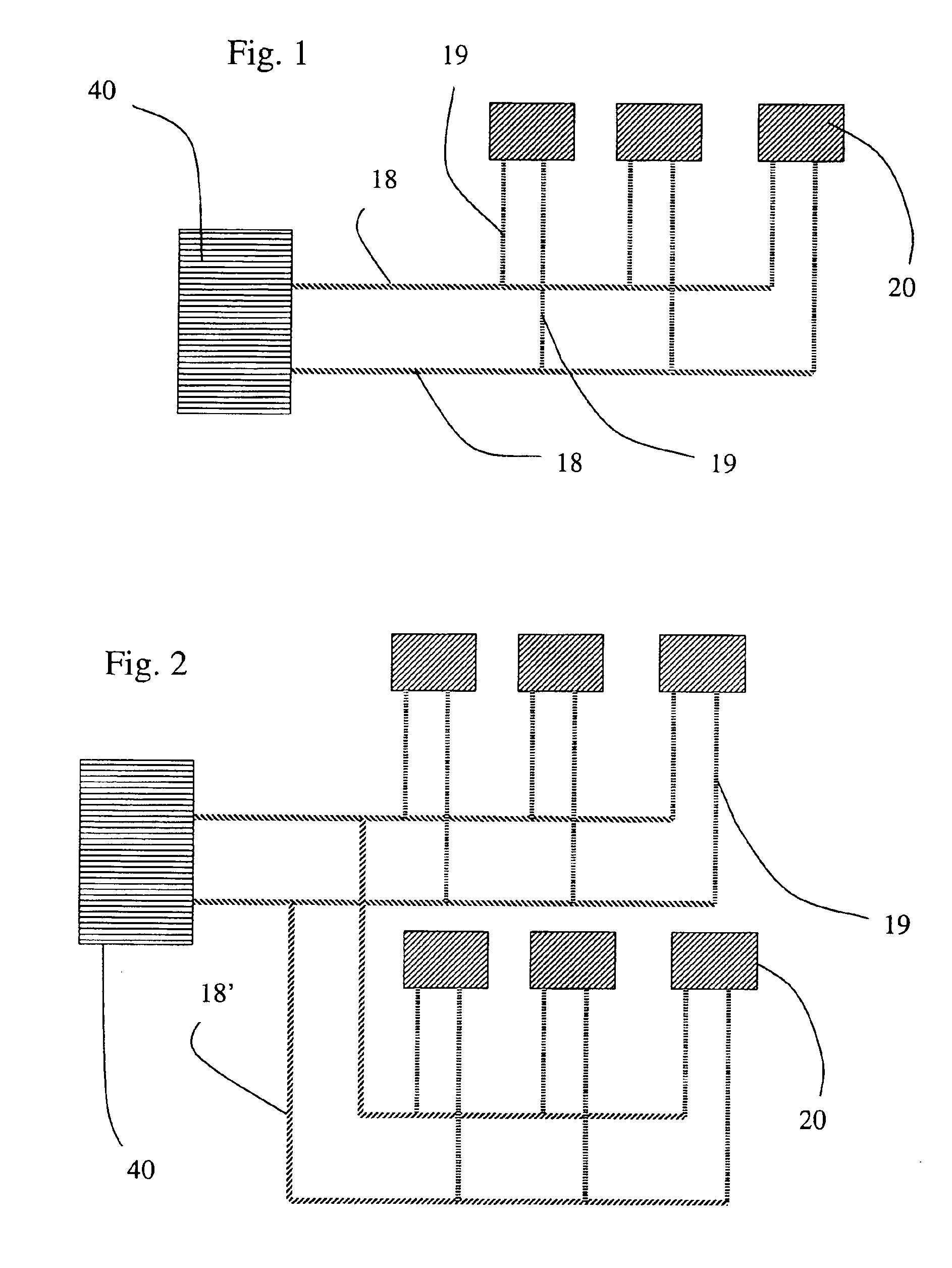
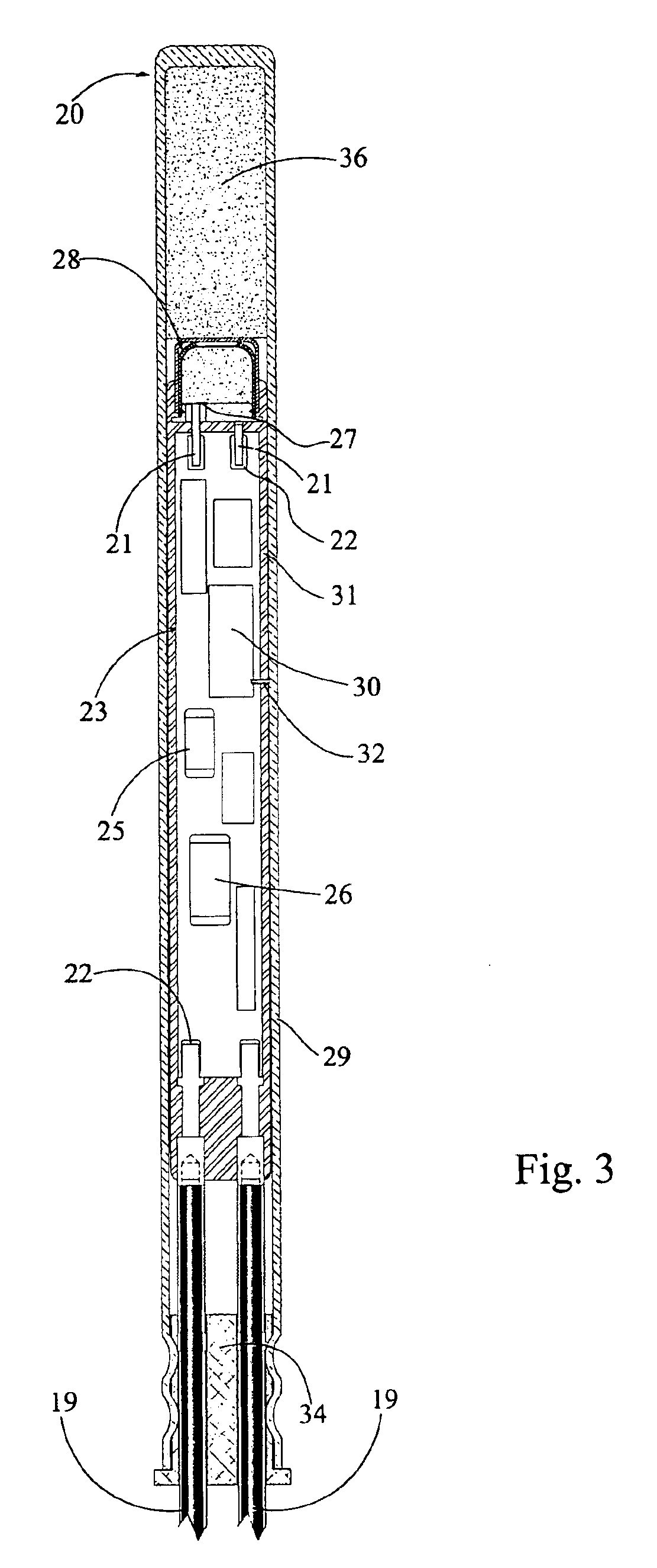
[0018]To describe the present invention with reference to the details of a particular preferred embodiment, it is noted that the present invention may-be employed in an electronic system comprising a network of slave devices, for example, an electronic blasting system in which the slave devices are electronic detonators. As depicted in FIG. 1, one embodiment of such an electronic blasting system may comprise a number of detonators 20, a two-line bus 18, leg wires 19 including connectors for attaching the detonator to the bus 18, a logger (not shown), and a blasting machine 40. The detonators 20 are preferably connected to the blasting machine 40 in parallel (as in FIG. 1) or in other arrangements including branch (as with the branched bus 18′ shown in FIG. 2), tree, star, or multiple parallel connections. A preferred embodiment of such an electronic blasting system is described below, although it will be readily appreciated by one of ordinary skill in the art that other systems or d...


PUM


Abstract

Regulated charging of an energy storage module in a pyrotechnic device such as a firing capacitor in an electronic detonator, preferably in the form of constant-current charging limited at a “rail voltage,” and optionally limited to a sufficiently low current to provide additional benefits to the pyrotechnic device such as in the case of a short-circuit.

Description

BACKGROUND OF THE INVENTION[0001]The present invention is directed generally to pyrotechnic devices, and more particularly, to a pyrotechnic device such as a detonator having regulated charging.[0002]Prior art detonators have not employed any current regulation in the charging of the firing capacitor. Without constant or regulated current during charging, however, excessive current may surge into the detonators' capacitors resulting in sagging of the bus due to IR drop and / or damage to the capacitors. The prior art has also included automatic charging of firing capacitors upon powering up of an electronic blasting system, but this can present safety concerns.SUMMARY OF THE INVENTION[0003]The present invention comprises the regulated charging of an energy storage module in a pyrotechnic device such as a firing capacitor in an electronic detonator. The regulation may preferably be in the form of constant-current charging limited at a “rail voltage,” wherein the amount of constant curr...

Claims


Application Information

Patent Timeline
Patent Type & Authority Patents(United States)
IPC IPC(8): F42D1/00F42D1/055F42B3/12F42B3/00
CPCF42D1/055F42B3/122
Inventor JENNINGS, III, DAVID T.
Owner AUSTIN STAR DETONATOR
Why Eureka
Try Eureka