Toner cartridge having a toner agitator and a reciprocally moving member coupled to the agitator, and an image forming apparatus
a technology of toner agitator and reciprocal moving member, which is applied in the direction of electrographic process apparatus, instruments, optics, etc., can solve the problems of fine shaft load, toner cartridge storage and mechanical vibration, and toner clumping
- Summary
- Abstract
- Description
- Claims
- Application Information
AI Technical Summary
Benefits of technology
Problems solved by technology
Method used
Image
Examples
first embodiment
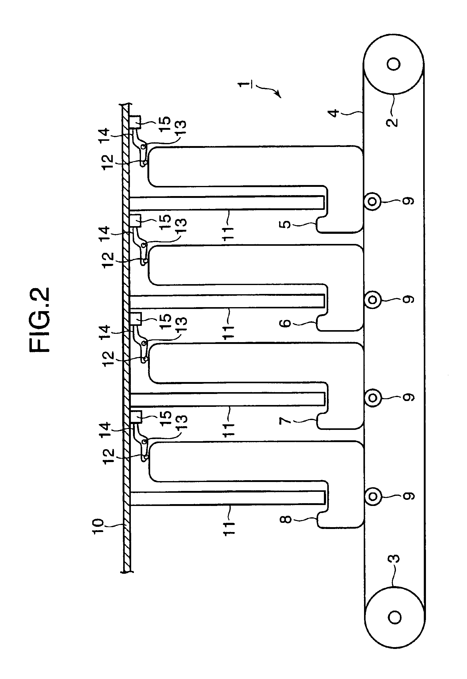
[0048]FIG. 2 is an illustrative diagram of an electrophotographic color recording apparatus according to a first embodiment.
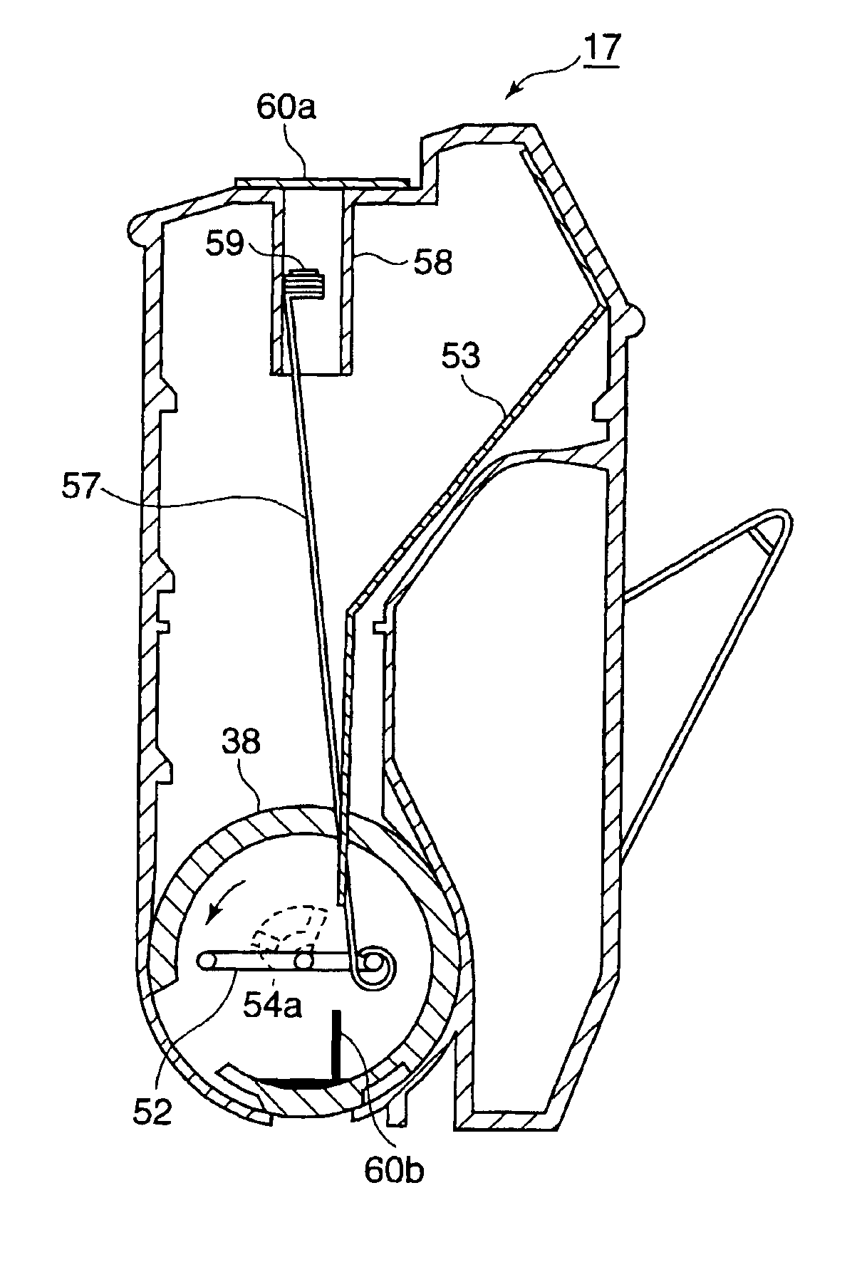
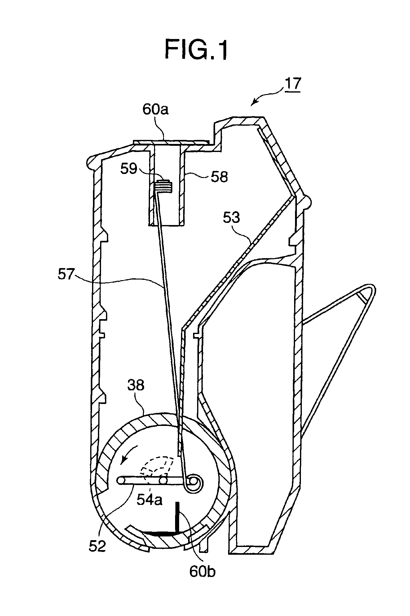
[0049]An electrophotographic recording apparatus 1 includes a medium-transporting belt 4, drive rollers 2 and 3, and image forming sections 5-8. The medium-transporting belt 4 extends in a direction in which the medium is transported. The transporting belt 4 is mounted about the drive rollers 2 and 3. The image forming sections 5-8 are aligned along the medium-transporting belt 4. The image forming sections 5-8 are of the same configuration and form yellow, magenta, cyan, and black images. The image forming sections 5-8 each include a print process cartridge 16 and a transfer roller 9. The transfer rollers 9 are aligned along the medium-transporting belt 4. The electrophotographic color recording apparatus has a cover 10. The cover 10 includes an exposing unit 11, a sensor lever 14, and a sensor 15. The sensor 15 takes the form of, for example, a photo sensor. ...
second embodiment
[0096]FIG. 19 is a perspective view of the sensor lever.
[0097]FIG. 20 illustrates the details of a coupling portion of a second lever.
[0098]A second embodiment differs from the first embodiment in that a second pivot shaft 80 is provided at one end of the sensor lever 14 so that the one end of the sensor lever 14 is pivotal about the pivot shaft 80. That is, the sensor lever 14 includes a first lever 14a and a second lever 14b. The first lever 14a and the second lever 14b are coupled through the pivot shaft 80. As shown in FIG. 20, the first lever 14a has a stepped portion 83 and a projection 82. As shown in FIG. 19, the second lever 14b has a groove 81 that fits the projection 82. A torsion spring, not shown, is mounted on the second pivot shaft 80 in such a way that end portions of the torsion spring abut the first lever 14a and the second lever 14b, respectively.
[0099]The operation will be described.
[0100]The operation of the second embodiment differs from that of the first embod...
third embodiment
[0101]FIG. 21 is a perspective view of a sensor rod according to a third embodiment.
[0102]The third embodiment differs from the first embodiment in that the sensor rod 90 is made of plastics and has a rectangular cross section. The sensor rod 90 has a first end coupled to the second crank 52b and a second end fixed to magnetic body 59, the second end sliding in the guide 58 provided on the upper wall of the body case 28. The guide 58 has inner surfaces on which the magnetic body slides. The guide 58 form cavity portions around the magnetic body. The guide 58 is cut away in part at their corners to form holes 92 so that the cavity portions 93 communicate the outside air through the holes 92. Thus, the guide 58 has holes 92 at the four corners, thereby minimizing areas of the guide 58 in contact with the sensor rod 90. The sensor rod 90 has a minimum area in contact with the guide 91. The sensor rod 90 reduces friction load exerted on the sensor rod 90 during the operation for detecti...
PUM
 Abstract
Description
Claims
Application Information
 - R&D
- Intellectual Property
- Life Sciences
- Materials
- Tech Scout
- Unparalleled Data Quality
- Higher Quality Content
- 60% Fewer Hallucinations
Browse by: Latest US Patents, China's latest patents, Technical Efficacy Thesaurus, Application Domain, Technology Topic, Popular Technical Reports.
© 2025 PatSnap. All rights reserved.Legal|Privacy policy|Modern Slavery Act Transparency Statement|Sitemap|About US| Contact US: help@patsnap.com


