
Charging device, process cartridge and image forming device

a charging device and process cartridge technology, applied in the direction of electrographic process equipment, instruments, corona discharge, etc., can solve the problems of increasing manufacturing time, increasing the cost of devices, uneven contact state with the electrified body in the generating line direction of the charging roller, etc., and achieves the effect of simple structure and simple method of production

Inactive Publication Date: 2005-05-03
RICOH KK
View PDF27 Cites 17 Cited by
  • Summary
  • Abstract
  • Description
  • Claims
  • Application Information

AI Technical Summary

Benefits of technology

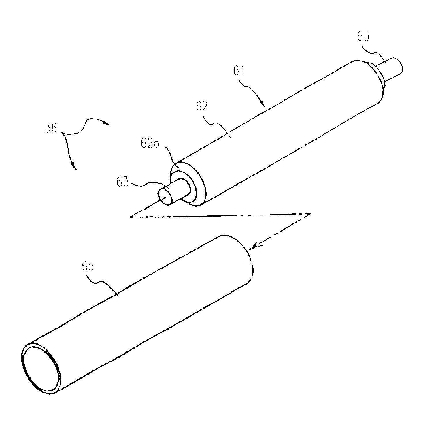
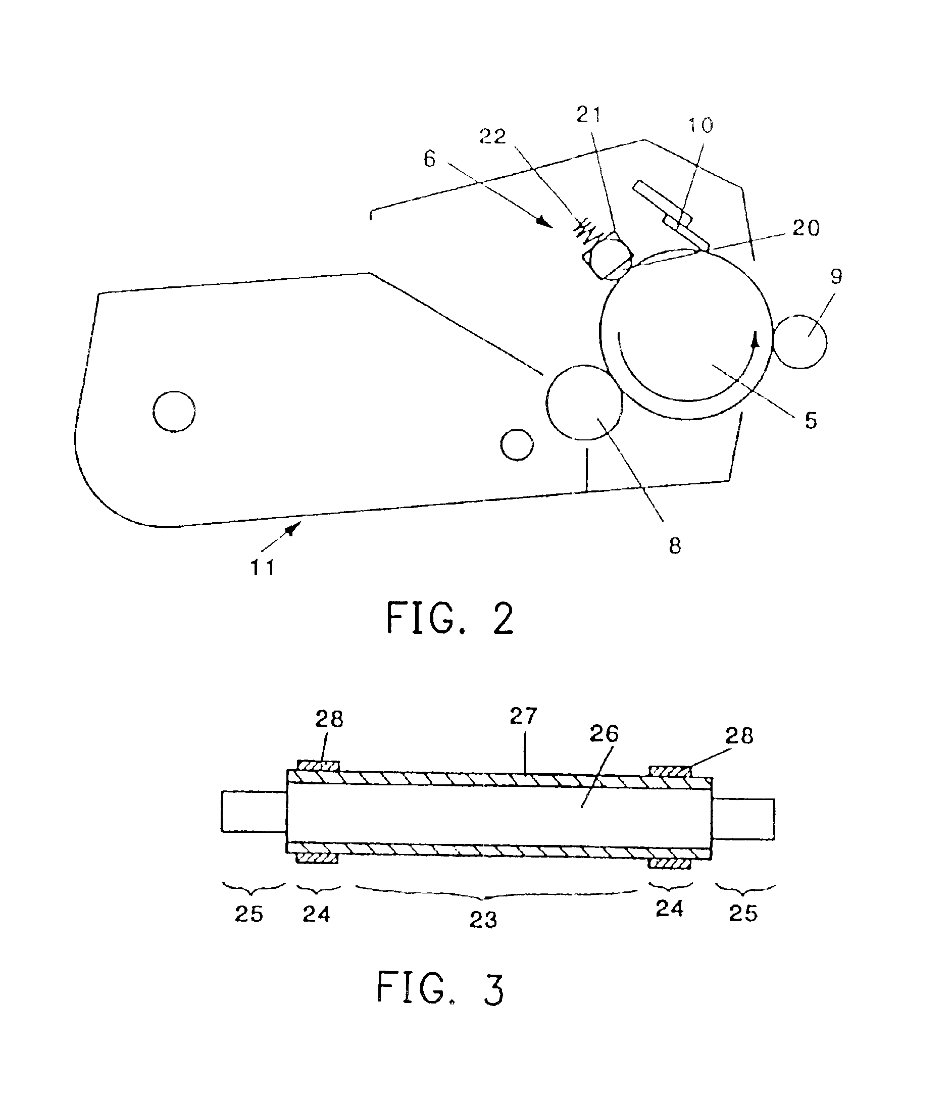
The present invention provides a conductive roller (charging roller) with a simple structure and low cost. The conductive roller has a thin film tube covering a core metal, and a single-layered resistant layer with a thickness of 0.7 mm and surface resistance between 1×10³ and 1×10¹⁵ Ω / □. The conductive unit can be used in an image forming device, charging device, process cartridge, and image forming device. The resistant layer can be made of a tube with a preset thickness and can be fixed onto the conductive base by thermal contraction. The conductive base can have a taper portion covering at least one end. The charging unit can have a bias including an AC bias and a DC bias. The charging device can be built into a process cartridge or an image forming device. The invention provides a simple and cost-effective solution for conductive rollers and charging units for image forming devices.

Problems solved by technology

When the contact charging process is executed on an electrified body such as the photoreceptor, if the straightness of the charging roller's edge line is not good, the contact state with the electrified body in the generating line direction of the charging roller becomes uneven.
In addition, the grinding amount is smaller than the target value, and the grounded dimension becomes large, which causes a bounce phenomenon.
Therefore, the manufacturing time is increased, and the device inevitably costs more.
The roller's shape cannot be completely controlled, causing a drawback of the roller having an uneven shape.
Because the roller shape's unevenness is increased in the grinding process, it is very difficult to maintain the air gap below 120 μm across the longitudinal direction of the roller.
In addition, even though the air gap can be maintained within 120 μm, charging unevenness might occur due to much gap unevenness.
Therefore, the manufacturing cost is increased.
In order to avoid the above problem, the metal shaft (as the core metal of the charging roller) is thickened to increase the rigidity etc., but problems, such as high cost and heavy weight, may occur.
Therefore, the cost is high and the shape unevenness is great.
Additionally, in view of contamination to the electrified body (the photoreceptor), a structure without the coating layer on the roller's surface is not practical.
When reusing the conductive base, removing the rubber layer is a time-consuming job, and therefore, the reproducing cost is increased.
However, when there occurs physical defects such as pinholes or cracks, since the roller is fixed by adhesive, replacing the roller needs time and therefore the cost increases.
In this case, the reuse is impossible and as a result, the conductive unit is wasted.

Method used


Image

  • Charging device, process cartridge and image forming device
  • Charging device, process cartridge and image forming device
  • Charging device, process cartridge and image forming device

Examples


Embodiment Construction

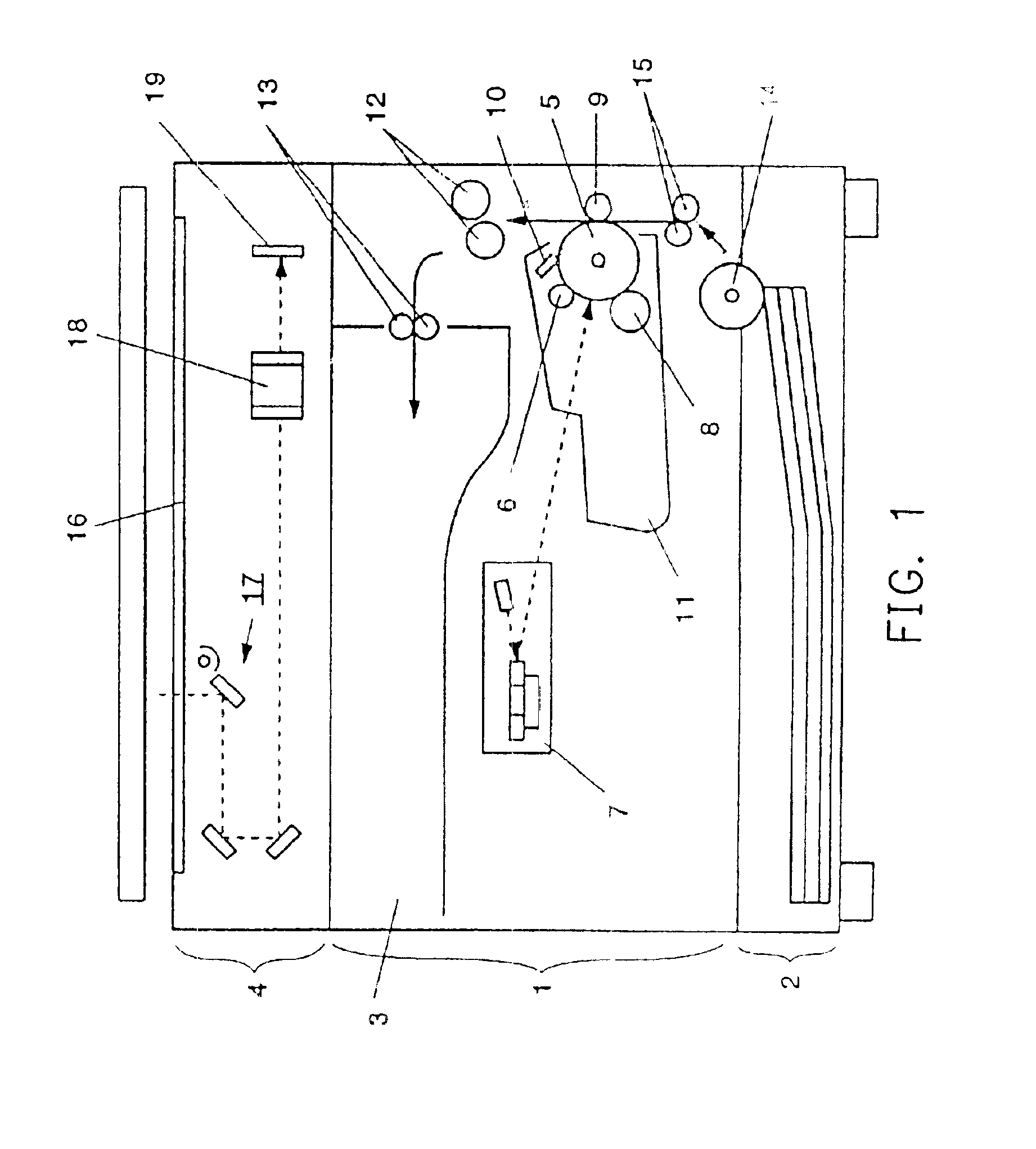
[0041]The detail description according to the preferred embodiments of the present invention is made with references to the accompanying drawings. The following description is an example of a charging device for a photoreceptor in an image forming device according to the present invention, but does not limit the scope of the present invention.

[0042]FIG. 1 is a schematic cross-sectional view showing the entire structure of an image forming device according to the invention. Because the image forming device shown in FIG. 1 is a type that stores the printed documents in paper ejection storage section 3, the image forming section 1 is substantially arranged at the center and a feeding unit 2 is arranged right under the image forming section 1. If necessary, an additional paper feeding unit can be further arranged under the paper feeding unit 2. A reading section 4 for reading a document is disposed above the image forming section 1 through a paper ejection storage section 3. The paper e...


PUM


Abstract

A charging unit, used for an image forming device, is provided, which comprises a conductive base, and a single-layered resistant layer, covering on a surface of the conductive base. The charging unit is in contact with an electrified body, and by applying a voltage to the conductive base, a charging process is performed in a contact charging manner. Furthermore, the single-layered resistant layer has a thickness equal to or below 0.7 mm, and has a surface resistance between 1×10³ (Ω / □) and 1×10¹⁵ (Ω / □). Therefore, a charging roller can be made with a very simple structure of the single-layered resistant layer surrounding the core metal, so that a cheap conductive roller can be provided. In addition, the charging unit can be spaced from the electrified body by a small gap and the resistant layer can include nylon.

Description

CROSS-REFERENCE TO RELATED APPLICATION[0001]This application claims the priority benefit of Japanese application serial no. 2001-255120, filed on Aug. 24, 2001 and 2001-279137, filed on Sep. 14, 2001.BACKGROUND OF THE INVENTION[0002]1. Field of the Invention[0003]This invention relates in general to an improvement of a charging roller used in an image forming device such as a copy machine, a printer, a facsimile device etc. using an electronic photographic process. More particular, the invention relates to a charging roller, which has a better productivity due to its simple structure and having an excellent recycling ability.[0004]2. Description of Related Art[0005]In an electronic photographic type image forming device, a photoreceptor is charged by a charging device such as a charging roller, and then by exposing the photoreceptor's surface, an electrostatic latent image is obtained. After the electrostatic latent image is developed by the toner provided from a developing device t...

Claims


Application Information

Patent Timeline
Patent Type & Authority Patents(United States)
IPC IPC(8): G03G15/02
CPCG03G15/025G03G15/0233
Inventor SUDA, TAKEOHARADA, HIROHMI
Owner RICOH KK
Learn More