Refinement of pitch detection

a pitch detection and pitch technology, applied in the field of pitch detection, can solve the problems of limiting the accuracy with which the pitch can be detected, computationally expensive calculation of error conditions, etc., and achieve the effect of increasing the resolution of sampled signals and allowing much more accurate pitch developmen

Inactive Publication Date: 2005-04-26
NXP BV +1
View PDF3 Cites 63 Cited by
  • Summary
  • Abstract
  • Description
  • Claims
  • Application Information

AI Technical Summary

Benefits of technology

[0011]It is an object of the invention to provide a method and apparatus of a kind set forth for determining successive pitch periods / frequencies in an audio equivalent signal, which enables accurate detection of the pitch at moderate computational requirements.
[0019]According to the invention, any suitable technique may be used to determine a rough estimate of the pitch. Following making the initial estimate, the signal is filtered to extract the lowest harmonic present in the signal. The filtering follows the determined rough pitch value. For instance, a band-pass filter may be constantly adjusted as the signal is passed through the filter to filter the band around the pitch frequency of the corresponding part of the signal. In this way a filtered signal is obtained which is highly dominated by the pitch frequency component. Using a suitable technique, an accurate estimate of the pitch is made based on the filtered signal. The estimating of the pitch detection can in itself be simple, for instance based on peak or zero crossing detection.
[0020]The initial rough estimate may be made using relatively large pitch detection segments of, for instance, 40 msec, in order to be able to detect any possible pitch frequencies. As part of the refinement, which follows making the rough estimate, new pitch refinement segments are created. The duration of the refinement segments is in principle independent of the duration of the pitch detection segments used for making the rough estimate. Particularly if the pitch detection segments were relatively large, the duration of the pitch refinement segments is chosen such to avoid too much smearing / averaging of the pitch. In this way the filtering is adjusted to accurately follow the development of the pitch, resulting in an accurately filtered signal.
[0022]In an embodiment according to the invention as described in the dependent claim 3, interpolation is used for increasing the resolution for sampled signals.
[0023]In an embodiment according to the invention as described in the dependent claim 4, the pitch refinement segment are created by displacing the time windows over a period that depends on the rough pitch estimate. For instance, the displacement of the windows to form the pitch refinement segment may correspond to a lowest measured pitch using the initial estimates, whereas the pitch detection segments were chosen at a fixed displacement of e.g. 40 msec. In this way, particularly for high pitched voices the pitch development can be followed much more accurately.

Problems solved by technology

Moreover, calculating the error condition is computationally expensive.
This results in smearing / averaging a change of pitch within such an interval, limiting the accuracy with which the pitch can be detected.

Method used


Image

  • Refinement of pitch detection
  • Refinement of pitch detection
  • Refinement of pitch detection

Examples


Embodiment Construction

Pitch Refinement

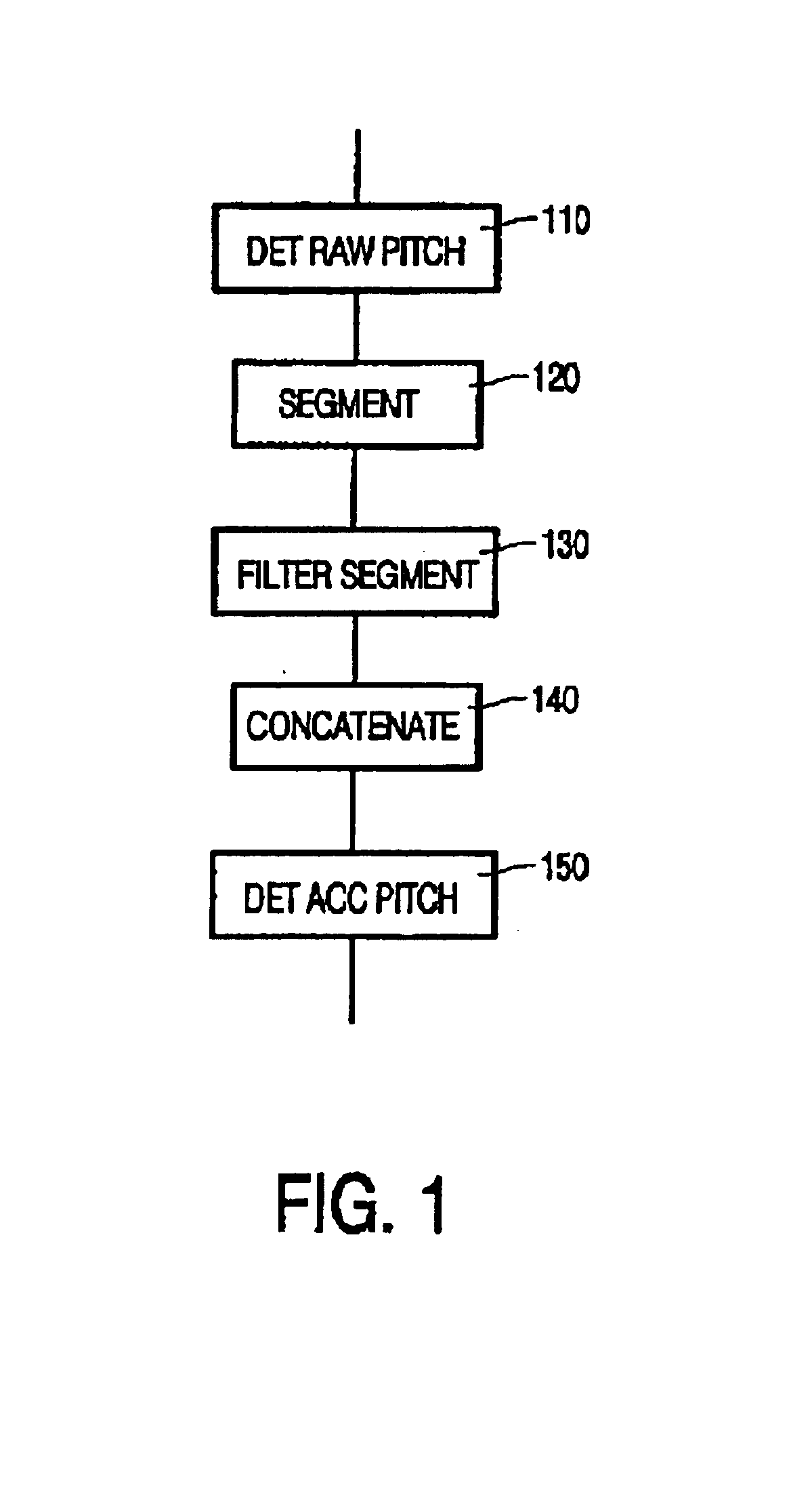
[0038]FIG. 1 illustrates accurately determining the pitch according to the invention. In step 110, a raw value for the pitch is obtained. In principle any suitable technique may be used to obtain this raw value. Preferably, the same technique is also used to obtain a binary voicing decision, which indicates which parts of the speech signal are voiced (i.e. having an identifiable periodic signal) and which parts are unvoiced. The pitch needs only be determined for the voiced parts. The pitch may be indicated manually, e.g. by adding voice marks to the signals. Preferably, the local period length, that is, the pitch value, is determined automatically. Most known methods of automatic pitch detection are based on determining the distance between peaks in the spectrum of the signal, such as for instance described in “Measurement of pitch by subharmonic summation” of D. J. Hermes, Journal of the Acoustical Society of America, Vol. 83 (1988), no.1, pages 257-264. Typically ...


PUM


Abstract

Successive pitch periods / frequencies are accurately determined in an audio equivalent signal. Using a suitable conventional pitch detection technique, an initial value of the pitch frequency / period is determined for so-called pitch detection segments of the audio equivalent signal. Based on the determined initial value, a refined value of the pitch frequency / period is determined. To this end, the signal is divided into a sequence of pitch refinement segments. Each pitch refinement segment is associated with at least one of the pitch detection segments. The pitch refinement segments are filtered to extract a frequency component with a frequency substantially corresponding to an initially determined pitch frequency of an associated pitch detection segment. The successive pitch periods / frequencies are determined in the filtered signal.

Description

BACKGROUND OF THE INVENTION[0001]The invention relates to a method of determining successive pitch periods / frequencies in an audio equivalent signal; the method comprising:[0002]dividing the audio equivalent signal into a sequence of mutually overlapping or adjacent pitch detection segments;[0003]determining an initial value of the pitch frequency / period for each of the pitch detection segments; and[0004]based on the determined initial value, determining a refined value of the pitch frequency / period.[0005]The invention further relates to an apparatus for determining successive pitch periods / frequencies in an audio equivalent signal, the apparatus comprising:[0006]segmenting means for forming a sequence of mutually overlapping or adjacent pitch detection segments;[0007]pitch detection means for determining an initial value of the pitch frequency / period for each of the pitch detection segments; and[0008]pitch refinement means for, based on the determined initial value, determining a r...

Claims


Application Information

Patent Timeline
IPC IPC(8): G10L11/00G10L11/04G10L25/90H03M7/30
CPCG10L25/90
Inventor GIGI, ERCAN F.
Owner NXP BV
Why Eureka
Try Eureka