
Green power supply system and green power supply method

a power supply system and green technology, applied in non-electric variable control, process and machine control, instruments, etc., can solve the problems of inability to know the influence of powers supplied to customers on global environmental loads, liable to destroy their surrounding ecological systems, and exhaustible resources of fossil fuels such as petroleum, coal and natural gas,

Inactive Publication Date: 2005-04-26
HITACHI LTD
View PDF6 Cites 39 Cited by
  • Summary
  • Abstract
  • Description
  • Claims
  • Application Information

AI Technical Summary

Benefits of technology

The present invention provides a power supply system and method that allows customers to use power while considering environmental loads and resource exhaustion. The system includes a part that receives customer requests for power generation, a part that stores power supply information, a part that calculates the green degree of power supply based on the customer's request and the power generation facilities' energy usage, and a part that notifies the customer or third party of the green degree of power supply. This invention helps to reduce environmental impact and promote economic activities.

Problems solved by technology

However, this related art only provides customers with a selection method which merely takes the price of power into account.
On the other hand, fossil fuels, such as petroleum, coal and natural gas, and uranium are exhaustible resources which will be completely consumed in the future.
In addition, burning fossil fuels produce carbon dioxide (CO2) which seems to be the cause of global warming.
Large-scale water power generation needs to build dams which are liable to destroy their surrounding ecological systems.
Customers have heretofore been unable to know the extent of the influences of powers supplied to the customers on global environmental loads, i.e., the amount of emission of CO2 which is based on the difference between the kinds of energy sources required for power generation, as well as the extent of exhaustion of energy sources.
In other words, customers' attempts at reducing global environmental loads have so far been limited to only the method of reducing electric power usage through energy saving, and customers have had few specific choices as to how they can actually promote the conservation of the beautiful earth.

Method used


Image

  • Green power supply system and green power supply method
  • Green power supply system and green power supply method
  • Green power supply system and green power supply method

Examples


Embodiment Construction

[0026]Preferred embodiments of a green power supply system and a green power supply method according to the present invention will be described below in detail with reference to the drawings

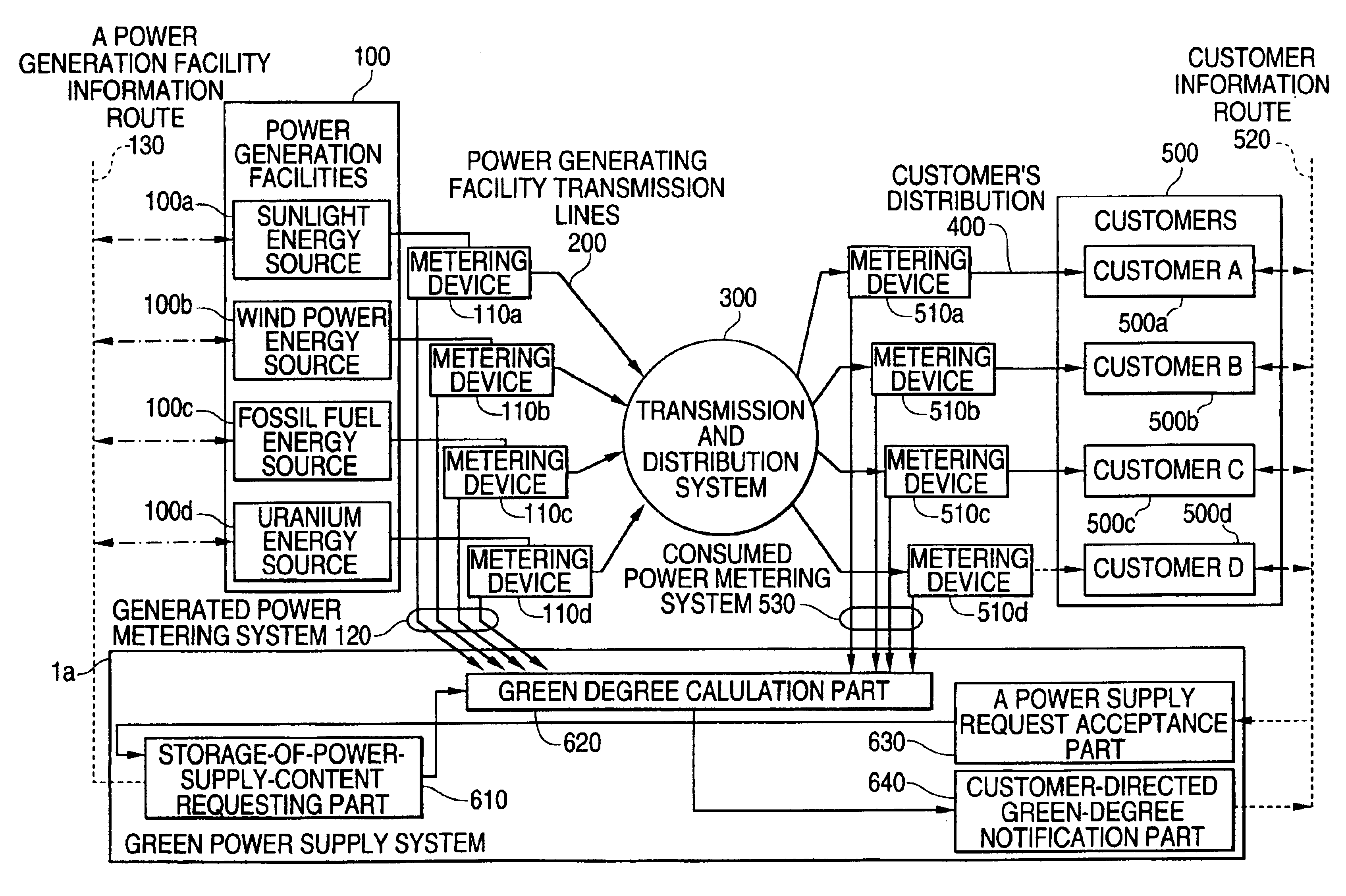
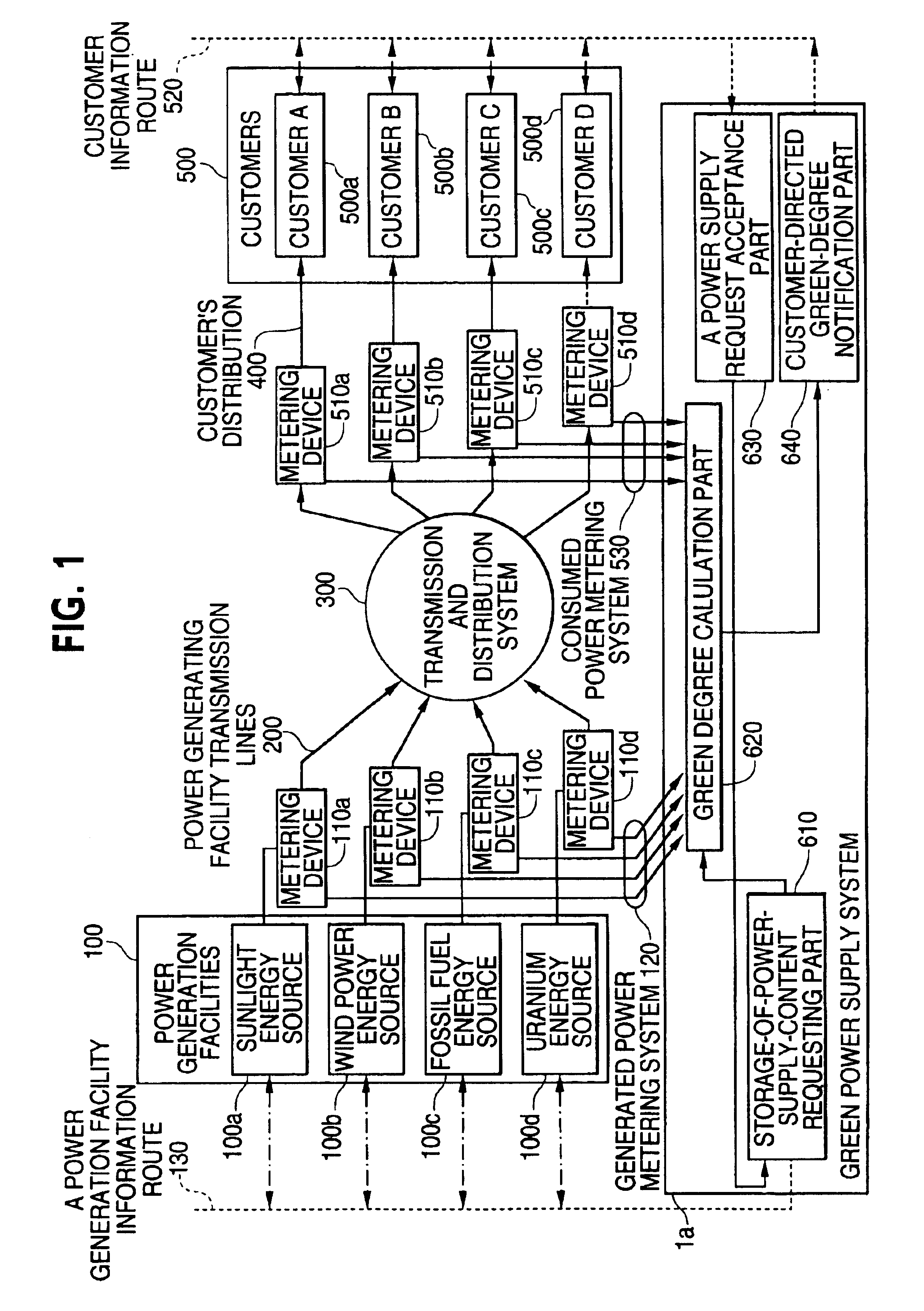
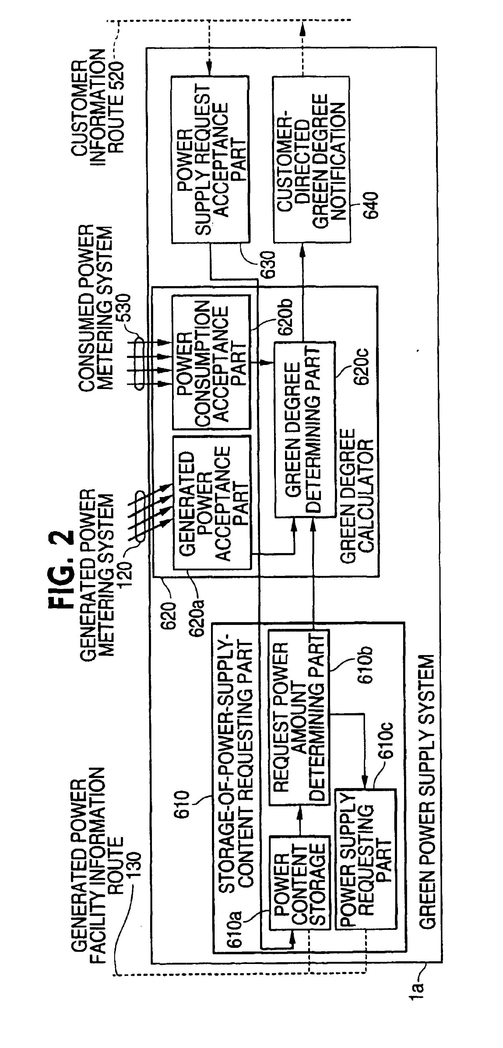
[0027]One embodiment of the present invention will be described below with reference to FIGS. 1 and 2. Representative examples of power generation energy sources to be used in power generation facilities are sunlight, wind power, tidal power, small-scale water power using no dam, biomass (biological resources), geothermal heat, waste heat utilization, waste such as burnt refuse, fossil fuels such as petroleum, coal and natural gas, and uranium. These examples have different influences on global environmental loads as well as different potentials for preventing the exhaustion of resources.

[0028]Reference numerals 100a, 100b, 100c and 100d denote power generation facilities which respectively use sunlight, wind power, fossil fuel and uranium fuel which are representative examples of power generatio...


PUM


Abstract

To permit a customer to reduce environmental load without reducing their electric power, a green power supply system is provided which includes a power supply request acceptance part which accepts from a customer a request to supply power having small environmental loads to the customer, a storage-of-power-supply-content requesting part which stores the state of power supply from each power generation facility, a green degree calculating part which determines the proportion of power which is supplied from the power generation facility having the small environmental loads, in power supplied to the customer, and a customer-directed green-degree notification part which notifies the customer of the degree of environmental load.

Description

[0001]This is a continuation of application Ser. No. 10 / 161,633 filed Jun. 5, 2002, now abandoned, which was a continuation of application Ser. No. 09 / 962,256, filed Sep. 26, 2001, now abandoned, the entire disclosures of which are hereby incorporated by reference.BACKGROUND OF THE INVENTION[0002]1. Field of the Invention[0003]The present invention relates to a power supply system and, more particularly, to a system and method which enable customers to select different types of power suppliers.[0004]2. Background Art[0005]A related art system which pertains to supplying power to customers on the basis of the conditions desired by the customers is described in Japanese Laid-Open No. 78747 / 2000, which is entitled “POWER COMPANY SELECTING METHOD AND SELECTION SUPPORT SYSTEM”.[0006]This related art pertains to the case in which different power companies have different charge systems, and enables a customer to select different contract conditions from each power company according to the ...

Claims


Application Information

Patent Timeline
Patent Type & Authority Patents(United States)
IPC IPC(8): H02J3/00G06Q50/00G06Q50/06
CPCH02J3/008H02J3/382H02J2003/007Y04S50/10Y04S40/22Y02E60/76Y02E10/763H02J3/386H02J2203/20H02J2300/40H02J2300/28H02J2300/20H02J3/381Y02E10/76Y02E60/00Y04S40/20
Inventor SHIMODE, SHINICHIFUKUI, CHIHIRO
Owner HITACHI LTD
Learn More