
Looper threading apparatus for sewing machine

a technology of looping apparatus and sewing machine, which is applied in the direction of sewing apparatus, loop taker, textiles and paper, etc., can solve the problems of clogging up the inner portion of the pipe, imposing a burden on the threading work, and affecting the work efficiency of the threading staff, so as to reduce the cost and reduce the size

Inactive Publication Date: 2005-04-19
JUKI CORP
View PDF6 Cites 14 Cited by
  • Summary
  • Abstract
  • Description
  • Claims
  • Application Information

AI Technical Summary

Benefits of technology

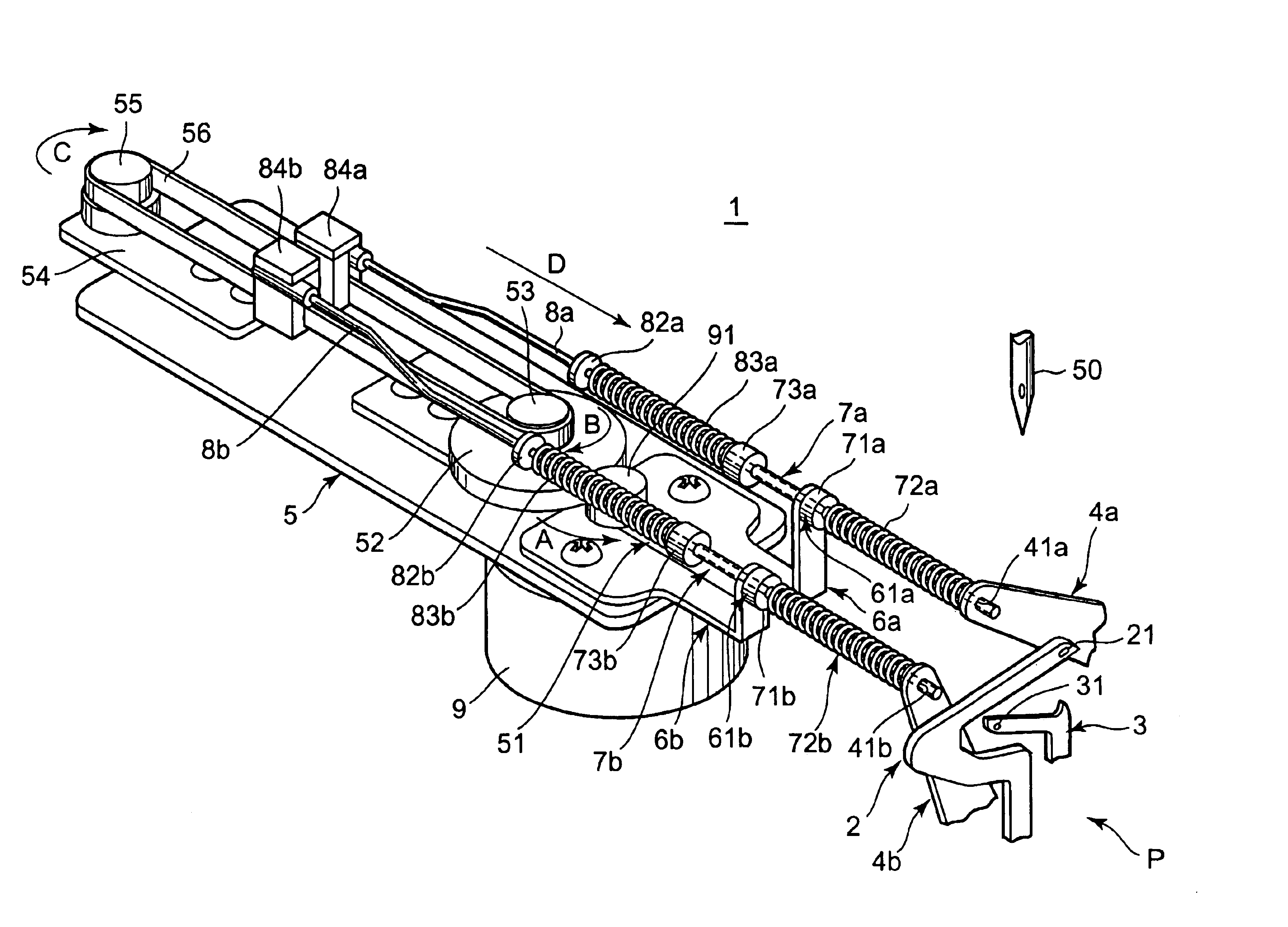
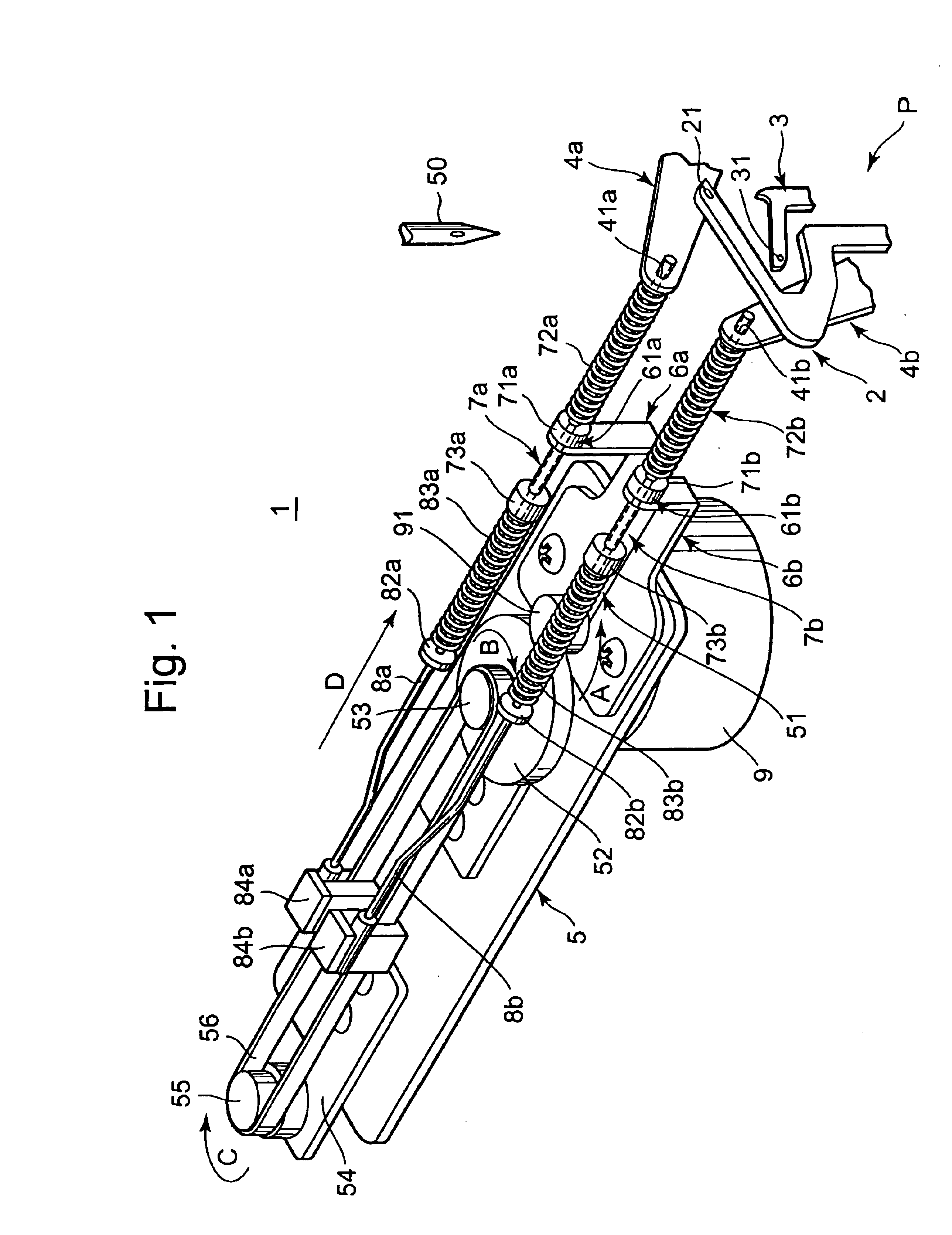
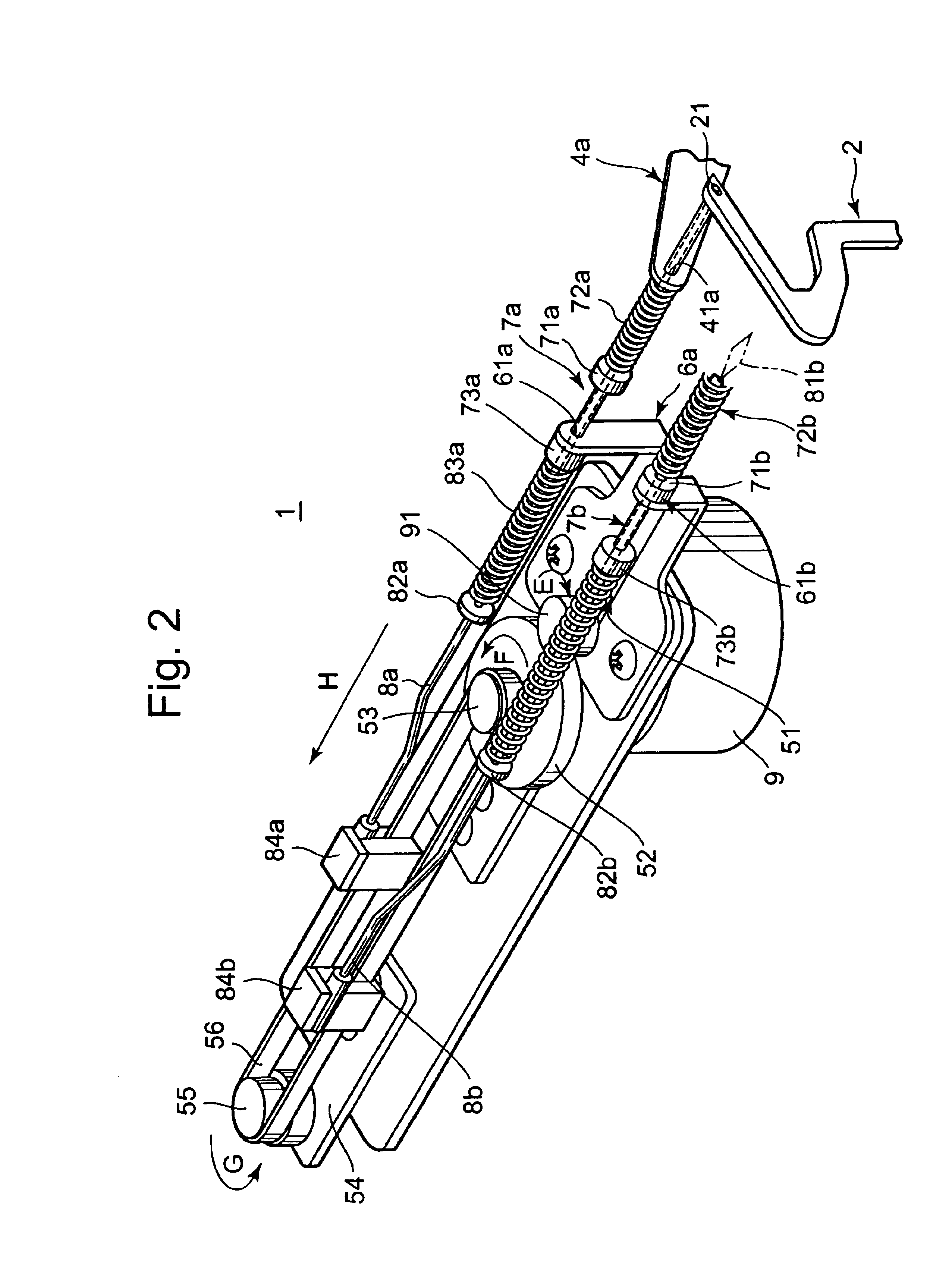
[0012]a guide member (for example, guide members 7a and 7b) for movably accommodating the threading member therein and guiding the threading member to the thread hole;
[0043]According to the tenth aspect of the invention, the threading members are moved by one moving mechanism. Therefore, it is possible to decrease a size and to reduce a cost.

Problems solved by technology

Therefore, a threading work imposes a burden, on an operator, and a working efficiency is not always high.
In the looper threading apparatus described in JP-A-06-277383, however, in some cases in which a foreign substance such as machine oil, a waste thread or dust enters a thread passage having a hollow structure, the inner portion of a pipe is clogged up and stagnated.
Consequently, a predetermined air flow for leading out the thread cannot be obtained.
As a result, there is a problem in that the thread cannot pass so that threading cannot be carried out or the foreign substance is stuck to the thread to be contaminated in the pipe.
While a thread guide and a thread tensioner are usually provided in the thread passage of the looper thread to influence a thread tension, furthermore, there is a problem in that the thread tension is affected so that a proper thread tension cannot be obtained and the quality of a sewn product is thereby deteriorated when the foreign substance is present in the pipe as described above.
Moreover, there is a problem in that a complicated work for removing these foreign substances from the inner part of the pipe and cleaning the dirty inner part of the pipe is required and a working efficiency is deteriorated.

Method used


Image

  • Looper threading apparatus for sewing machine
  • Looper threading apparatus for sewing machine
  • Looper threading apparatus for sewing machine

Examples


first embodiment

[First Embodiment]

[0056]A looper threading apparatus for a sewing machine according to embodiments will be described with reference to FIG. 1 to FIG. 5 and FIG. 9 to FIG. 11.

[0057]In a domestic overcasting sewing machine to be a sewing machine according to the embodiment, as shown in FIG. 9 and FIG. 1, a sewing machine body portion Ma and a bed portion Mb are provided on right and left sides respectively as seen from an operator side (an arrow P), and a needle 50 to be vertically moved interlockingly with the main shaft of the sewing machine which is not shown and a lower looper 2 and an upper looper 3 which are swung interlockingly with the main shaft of the sewing machine are provided on the sewing machine body portion Ma side, and a stitch can be formed by the cooperation of the needle 50 and the lower looper 2 and upper looper 3. The tips of the lower looper 2 and the upper looper 3 have slot-shaped thread holes 21 and 31 through which the thread is inserted, respectively. A loo...

second embodiment

[Second Embodiment]

[0096]Next, a looper threading apparatus according to a second embodiment will be described with reference to FIGS. 6 to 8. In the looper threading apparatus according to the embodiment, the catching portions of the threading members 8a and 8b are changed in the looper threading apparatus 1 according to the first embodiment, and other structures are substantially identical to those in the first embodiment. In the following description, therefore, common structures to the looper threading apparatus 1 according to the first embodiment have the same reference numerals.

[0097]As shown in FIG. 6, a catching portion 85a of the threading members 8a and 8b according to the embodiment is formed like a rod having a narrow tip and a side surface thereof is provided with a holding groove 86a for holding a thread T. When the catching portion 85a is inserted through a thread hole 21, the thread T is engaged with the holding groove 86a as shown in FIG. 7. By the retreat of the th...


PUM


Abstract

A looper threading apparatus includes a threading member capable of holding a thread in a tip portion and inserting the thread through a thread hole, a guide member for movably accommodating the threading member and guiding the threading member to the thread hole, and a support member for supporting the guide member to freely approach and separate from the thread hole provided on an extended line of the threading member accommodated by the guide member. Moreover, there is provided a moving mechanism for moving the threading member and the guide member along an axis of the thread hole provided on the extended line. The moving mechanism moves the guide member and the threading member with respect to the thread hole provided on the extended line in such a manner that the tip portion of the threading member penetrates through the thread hole.

Description

BACKGROUND OF THE INVENTION[0001]The present invention relates to a looper threading apparatus for a sewing machine for threading for a thread hole provided on a looper to be swung in order to form a stitch in cooperation with the needle of the sewing machine.[0002]Conventionally, an overcasting overlock sewing machine and a multi-thread chain stitch sewing machine comprise a looper for reciprocating while drawing an arcuate track to cross the track of a needle according to the vertical motion of the needle. A looper thread led by the looper forms a stitch together with a needle thread.[0003]Threading for the looper is usually carried out manually by using a pair of tweezers. A thread hole formed on the looper is small. Therefore, a threading work imposes a burden, on an operator, and a working efficiency is not always high.[0004]In recent years, in order to enhance the efficiency of the threading work for a looper, a looper threading apparatus for carrying out threading by utilizin...

Claims


Application Information

Patent Timeline
Patent Type & Authority Patents(United States)
IPC IPC(8): D05B87/00D05B87/02
CPCD05B87/02
Inventor HORIUCHI, TOSHIO
Owner JUKI CORP
Learn More