
Medical device with dual communications bus

a communication bus and medical device technology, applied in the field of medical devices, can solve the problems of additional software, unnecessary long periods of data communication, and objections of a different kind to modular internal communication, and achieve the effect of simple, fast and reliable programming operation

Inactive Publication Date: 2005-04-12
FRESENIUS MEDICAL CARE DEUTSCHLAND GMBH
View PDF16 Cites 43 Cited by
  • Summary
  • Abstract
  • Description
  • Claims
  • Application Information

AI Technical Summary

Benefits of technology

The object of the invention is to improve in such a manner a generic medical device that a simple, fast and reliable programming operation, test sequence run, diagnosis and / or maintenance of the end devices, located at the two buses, are possible.
With the aid of the system, according to the invention, it is possible to connect the two communications buses, whenever an external device for programming, for implementing test sequences, for diagnosis and / or for maintenance is supposed to be connected to the system, in order to form a uniform communications bus, with the result that simple, fast and more reliable connecting paths are provided that can be separated again safely and reliably after these process steps.
The invention is also based on the problem of providing a method for a simple fast and reliable programming, test, diagnosis and / or maintenance operation of a generic medical device with an interface to an external device.

Problems solved by technology

However, the computer architecture of this device exhibits the following drawback.
The internal computer connection turns out to be a bottleneck with respect to the data transfer rate, resulting in unnecessary long periods for data communications.
However, there are also objections of a different kind against modular internal communication.
Furthermore, each computer must have additional software to even handle the data transfer.
In this respect the operation is altogether time consuming and error prone.
To access the internal bus from the main data bus for test purposes, there are bidirectional logic means, which exhibit, however, a complicated design.
The EP 0 306 211 A2 describes a very expensive, synchronized twin computer system.

Method used


Image

  • Medical device with dual communications bus
  • Medical device with dual communications bus

Examples


Embodiment Construction

Further scope of applicability of the present invention will become apparent from the detailed description given hereinafter. However, it should be understood that the detailed description and specific examples, while indicating preferred embodiments of the invention, are given by way of illustration only, since various changes and modifications within the spirit and scope of the invention will become apparent to those skilled in the art from this detailed description.

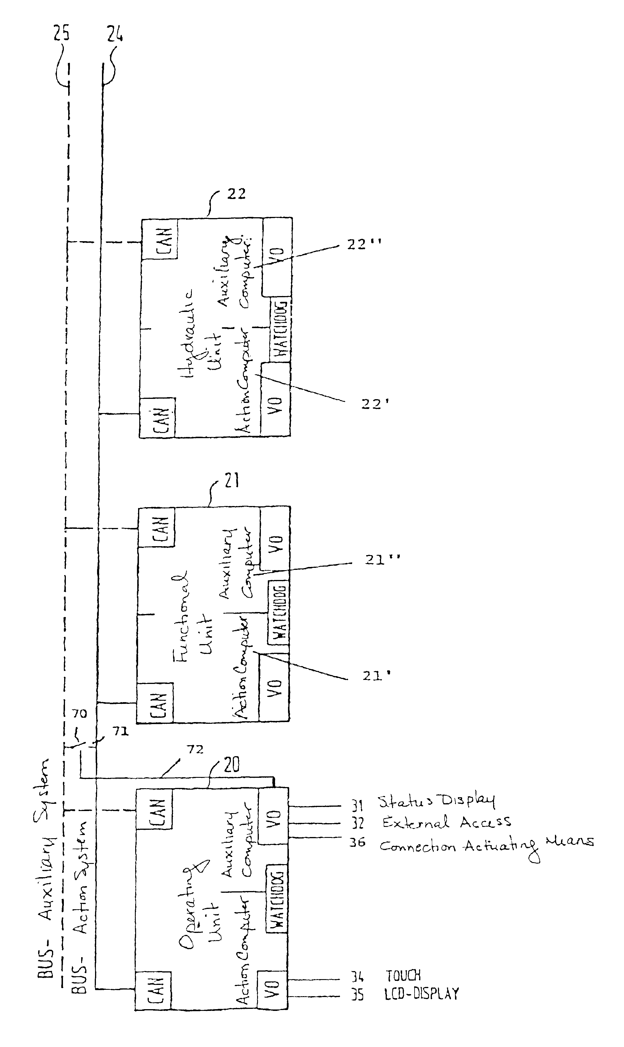
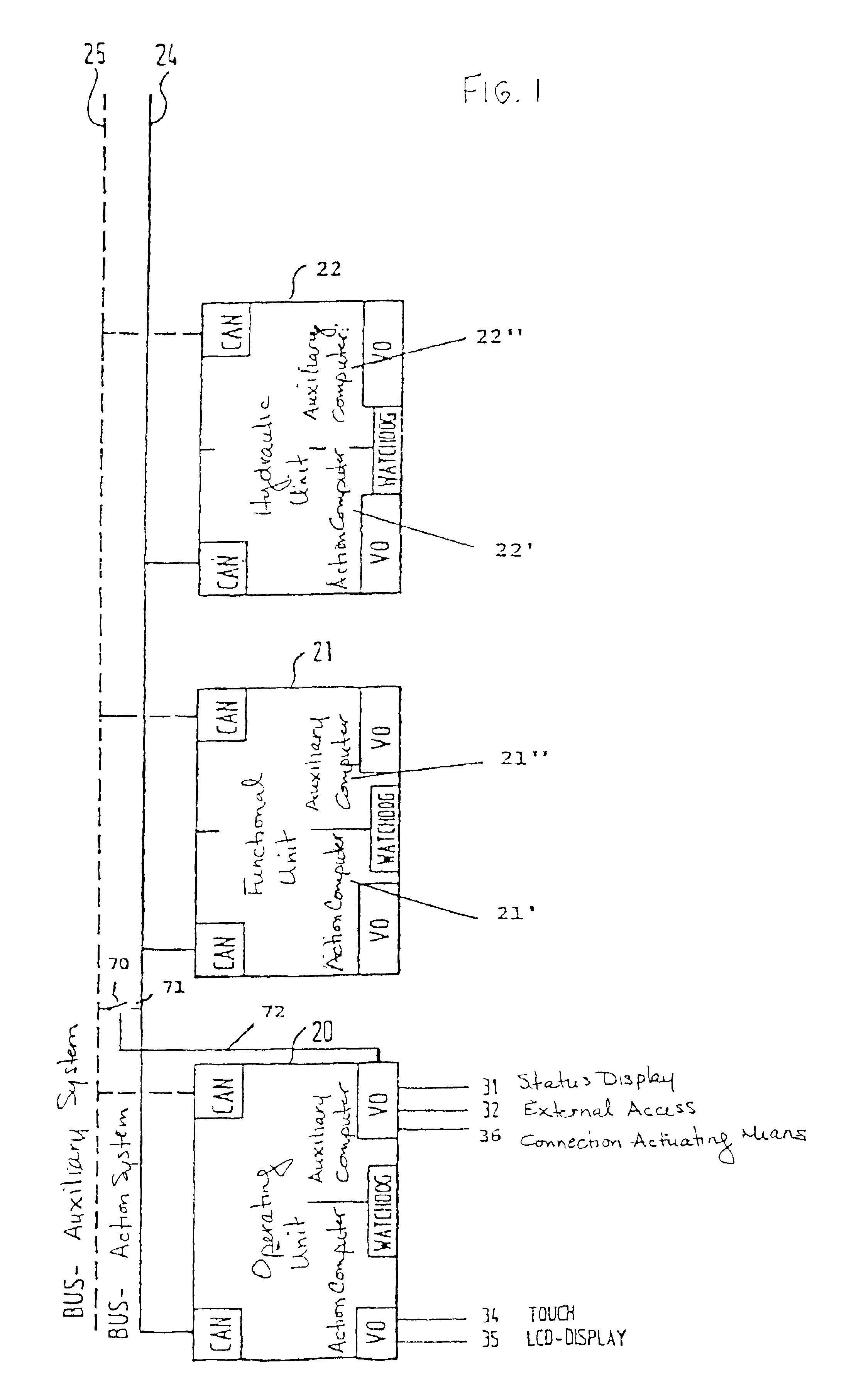
FIG. 1 depicts the computer structure of a hemodialysis unit, according to DE 198 49 787 C1. To the extent that it is not absolutely necessary for understanding the invention, the actuators and sensors of the individual units were omitted for the sake of a better overview. However, such details are disclosed in the DE 198 49 787 C1.

The computer structure of the hemodialysis machine exhibits an operating unit 20 with an action computer 20′ with a touch screen 34 as the input means and an LCD display 35 as the output mea...


PUM


Abstract

A medical appliance having an auxiliary computer system in addition to its action computer system, and further having two communications buses. The auxiliary computer system independently monitors the functional mode of the action computer system and can induce a reliable state of the appliance in an emergency. To easily, quickly and reliably implement a programming, the execution of test sequences, the diagnosis and the maintenance of such an appliance, a connection line, which can be interrupted by a switch, is arrange between the communication buses, and both communications buses can be connected to form a unified communications bus via the communication line. A method for executing such a programming process, testing process, diagnostic process and / or maintenance process of a medical appliance is also provided.

Description

BACKGROUND OF THE INVENTION1. Field of the InventionThe invention relates to a medical device having at least two units for monitoring and / or controlling thereof, and two communications buses. The units include at least one computer with a microprocessor, and at least one unit having a second computer with a second microprocessor, with each of the computers being attached to either the first or the second communications bus. The invention is also directed to a method for the programming, the implementation of the test sequences, the diagnosis and maintenance of such a device.2. Description of the Related ArtSuch medical devices often exhibit a computer architecture with two communications buses. Such a computer architecture is generally appropriate when, in addition to the action computer system, a medical device needs for safety requirements an auxiliary computer system that monitors independently the operating mode of the action computer system and in the event of an emergency can...

Claims


Application Information

Patent Timeline
Patent Type & Authority Patents(United States)
IPC IPC(8): A61M1/16G06F19/00H04L12/12A61M1/14
CPCA61M1/16H04L12/12G06F19/3412A61M2205/3584Y02B60/34G16H40/40Y02D30/50
Inventor MANKE, JOACHIMSCHEUNERT, PETER
Owner FRESENIUS MEDICAL CARE DEUTSCHLAND GMBH
Learn More