Eureka AIR delivers breakthrough ideas for toughest innovation challenges, trusted by R&D personnel around the world.

Multifunctional modular robot head

A robot and multi-functional technology, applied in manipulators, program-controlled manipulators, manufacturing tools, etc., can solve the problems of poor interchangeability of internal structures, poor interchangeability and versatility, and inability to achieve comprehensive compatibility, so as to reduce comprehensive costs and shorten cycle, the effect of structure simplification

Inactive Publication Date: 2019-01-04
深圳全智能机器人科技有限公司
View PDF6 Cites 1 Cited by
  • Summary
  • Abstract
  • Description
  • Claims
  • Application Information

AI Technical Summary

Problems solved by technology

[0004] 1. The structure is simple: it cannot simulate realistic physical movements, for example, it cannot cooperate to complete a series of man-machine communication actions such as opening the mouth to speak, opening the eyes to take pictures, nodding or shaking the head, and turning the eyes left and right;
[0005] 2. The internal structure is poorly interchangeable and cannot be used universally. For example, the same skull structure cannot be used in common with other masks. The mask can only be configured with the skull structure, which cannot meet the design needs of different appearances and expressions. It is difficult to achieve To meet the needs of customer customization, each company is basically different for the interface between the torso and the head, and the interchangeability and versatility are poor, and the goal of comprehensive compatibility cannot be achieved.

Method used


Image

  • Multifunctional modular robot head
  • Multifunctional modular robot head
  • Multifunctional modular robot head

Examples


Embodiment

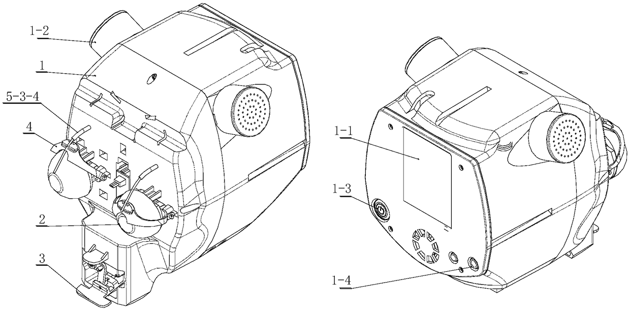
[0042] Such as figure 1 Shown is the head structure of the robot in this scheme, including the mask 1, eyeball 2, lip 3 and eyelid 4, the eyeball 2, lip 3 and eyelid 4 are arranged on one side of the mask 1 and respectively connected to the drive structure on the other side of the mask 1 5 connection; the driving structure 5 includes the eyeball driving mechanism 5-1;

[0043] In order to realize two actions by one power source (steering gear) and save costs; the eyeball drive mechanism 5-1 designed with a linkage link is adopted to make the left and right eyes rotate synchronously and in harmony;

[0044] Such as Figure 3-5Shown is the eyeball driving mechanism 5-1, including: eyeball fixing frame 5-1-1, the first steering gear 5-1-2, the first swing arm 5-1-3 and the first connecting rod 5-1-4 ; The number of the first connecting rod 5-1-4 is 2 and is composed of a horizontal connecting rod 5-1-4-1 and a vertical connecting rod 5-1-4-2 connected to each other, and the eye...


PUM

PropertyMeasurementUnit
Rotation angleaaaaaaaaaa

Abstract

The invention relates to a multifunctional modular robot head which comprises a mask, eyeballs, lips and eyelids. The eyeballs, the lips and the eyelids are arranged on one side of the mask and connected with a driving structure on the other side of the mask. The driving structure comprises an eyeball driving mechanism, a lip driving mechanism and an eyelid driving mechanism. The eyeball driving mechanism comprises eyeball fixing frames, a first actuator, first swing arms and first connecting rods. The lip driving mechanism comprises a second actuator, second swing arms and second connecting rods. The eyelid driving mechanism comprises third actuators, third swing arms, steel wire ropes and hard rubber tubes for restraining sliding tracks of the steel wire ropes. According to the scheme, linkage connecting rod design is adopted, the left and right eyeballs rotate synchronously, the vertical swing amplitude of the lips right accords with the opening-closing amplitude of a real person, eyelid blinking is achieved through the structure that the steel wire ropes are sleeved with the hard rubber tubes, and the requirement that push-pulling actions and micro-deformation are both requiredis well met through flexibility of the steel wire ropes and restraining of the hard rubber tubes.

Description

technical field [0001] The invention relates to a mechanical head structure, in particular to a multifunctional modular robot head. Background technique [0002] At present, there are robot heads, which mainly adopt an integrated design structure. However, the interface between the torso and the head is different for each company. Each mechanical head must be equipped with a specific mask, specific interface and driving method, etc.; the current The mechanical head is mainly used in the following types of robots: 1. Service and escort robots. The structural design of this mechanical head generally adopts a fixed-mode cartoon shape, and can only perform simple actions such as shaking the head, and cannot achieve high-simulation simulation actions; 2. Welcome Bin robot, although this kind of head structure can realize part of the action function of simulating human beings; however, its interior adopts an integrated structure design, and it cannot be adjusted as needed in terms...

Claims


Application Information

Patent Timeline
IPC IPC(8): B25J9/00B25J9/08
CPCB25J9/00B25J9/0009B25J9/08
Inventor 王绍芳
Owner 深圳全智能机器人科技有限公司
Why Eureka
Eureka Blog
Learn More