Radiation emission device and method

a radiation emission device and emission technology, applied in the direction of instruments, x-ray tube targets and convertors, x-ray tubes, etc., can solve the problems of reducing the resolution of radiographic images that can be obtained, limiting the resolution of films obtained from x-ray sources, and appearing of additional vibrations

Inactive Publication Date: 2005-04-12
GE MEDICAL SYST GLOBAL TECH CO LLC
View PDF8 Cites 3 Cited by
  • Summary
  • Abstract
  • Description
  • Claims
  • Application Information

AI Technical Summary

Benefits of technology

An embodiment of the invention is also directed to a computer program capable of being loaded on a memory of a microprocessor including program code means making possible the use of an X-ray emission device intended for a radiology apparatus, when it is executed by a microprocessor, the X-ray emission device comprising a cathode and a rotating anode, the anode being provided with a roughly cylindrical surface and the device being capable of forming a beam of electrons that bombard a portion of the roughly cylindrical surface of the anode constituting the X-ray emission focal point. The program code means comprise a module for processing the measurement made by a detection means and a control module making it possible to elaborate a control signal for dynamically controlling the position of the focal point relative to a reference position, as a function of a signal supplied by the processing module.

Problems solved by technology

This displacement is due in part to the geometric defects of the anode.
Furthermore, the increase in temperature of the X-ray tube produces expansion of the different components of the X-ray tube, an expansion that can cause the appearance of additional vibrations and the deformation of some of the elements producing a variation of distance between the cathode and the surface of the anode forming the focal point.
The position defect of the focal point produces a widening of the apparent X-ray source or loss of space resolution of the focal point, thus diminishing the resolution of a radiographic image that can be obtained.
A loss of space resolution limits the resolution of a film obtained from the X-ray source, and renders the detection of microcalcifications of small dimensions more difficult.
Furthermore, the device does not make it possible to correct the position of the focal point radially.

Method used


Image

  • Radiation emission device and method
  • Radiation emission device and method
  • Radiation emission device and method

Examples


Embodiment Construction

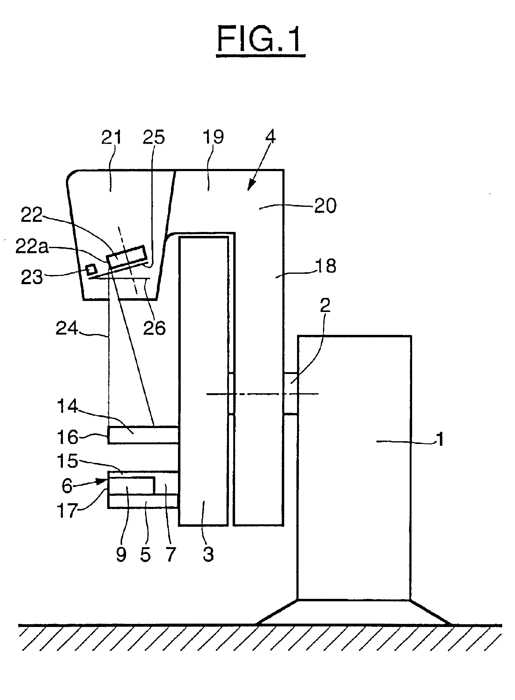
In FIG. 1, a mammography apparatus comprises a base 1 standing on the floor, supporting through a horizontal axis 2; a fixed vertical support column 3, placed at the end of the axis 2 opposite the base 1; and an assembly 4 rotating on the axis 2. A platform 5 extends horizontally from the column 3, on the side opposite the base 1, and serves as a support for an assembly 6 comprising a flat support member 7 extending in a horizontal plane and resting on the platform 5.

A receiver 9 is placed in the plane of the support member 7 horizontally at the end of the support member 7 opposite the support column 3. A compression member 14 attached to the support column 3, movable vertically relative to the support column 3, extends horizontally from the support column 3 in an area situated vertically facing a fixed surface 15 of the support 7 located above the receiver 9. The end 16 of the compression member 14 opposite member 11 is situated vertically roughly at the same level as an end 17 of ...


PUM


Abstract

An X-ray emission device and method for a radiology apparatus comprises a cathode and a rotating anode, the anode being provided with a roughly cylindrical surface. The device forms a beam of electrons that bombards a portion of the roughly cylindrical surface of the anode that constitutes the focal point of emission of the X-rays. The position of the focal point of the anode relative to a reference position is dynamically controlled.

Description

CROSS-REFERENCE TO RELATED APPLICATIONSThis application claims the benefit of a priority under 35 USC 119 to French Patent Application No. 01 11383 filed Sep. 3, 2001 the entire contents of which are hereby incorporated by reference.BACKGROUND OF THE INVENTIONThe present invention concerns a radiation emission device, for example, an X-ray emission device, which can be used, for example, in the field of medical imaging. A radiography apparatus, used for mammography, for example, comprises an X-ray tube and a collimator for forming and delimiting an X-ray beam, an image receiver. A positioner, bearing the assembly, comprises the X-ray tube and the image receiver, the assembly being movable in space on one or more axes. EP-A-972 490 discloses such an apparatus.As is standard, for the purpose of screening for possible breast cancers, X-rays of the breast are taken to obtain images that are analyzed in order to deduce the likelihood of presence of a malignant lesion. The lesions are gen...

Claims


Application Information

Patent Timeline
Patent Type & Authority Patents(United States)
IPC IPC(8): H01J35/02H01J35/00H05G1/00
CPCH01J35/02H05G1/00H01J2235/08H01J35/24H01J35/28H01J2235/10H01J2235/1073H01J2235/1204H05G1/52
Inventor BLIN, PHILIPPELE PENNEC, XAVIERDAHAN, FREDERIC
Owner GE MEDICAL SYST GLOBAL TECH CO LLC
Why Eureka
Try Eureka