
Passive clearance control

a technology of clearance control and control panel, which is applied in the direction of machines/engines, liquid fuel engines, lighting and heating apparatus, etc., can solve the problems of engine efficiency deficit, engine complexity, loss of energy, etc., and achieves simple manufacturing and assembly, long operating life, and easy maintenance

Active Publication Date: 2005-04-12
FLORIDA TURBINE TECH
View PDF2 Cites 81 Cited by
  • Summary
  • Abstract
  • Description
  • Claims
  • Application Information

AI Technical Summary

Benefits of technology

This invention is characterized as being relatively simple to manufacture and assemble, easy to maintain, relatively inexpensive and should have a long operating life.

Problems solved by technology

Obviously, the leakage represents loss of energy that has been added to the engine working medium and represents a deficit in engine efficiency.
Of course, the down side of the active clearance control is that it adds complexity to engine, requires valving and moving parts, a control system and in many installations it requires piping that surrounds the engine case to shower the case with cooling air to effectuate the contraction thereof.
One of the major obstacles that the designer needs to overcome is the selection of a system that will contemplate the relatively faster expansion / contraction of the lower mass blades and the slower expansion / contraction of the disc supporting the blades.
Notwithstanding the advances made in this technology, all of the systems alluded to in the above paragraphs do not achieve a relatively constant clearance during the transient operation of the engine.
Hence, if the gap increased during the transient, there will be an increase in leakage of the engine working medium flowing through this gap.

Method used


Image

  • Passive clearance control
  • Passive clearance control
  • Passive clearance control

Examples


Embodiment Construction

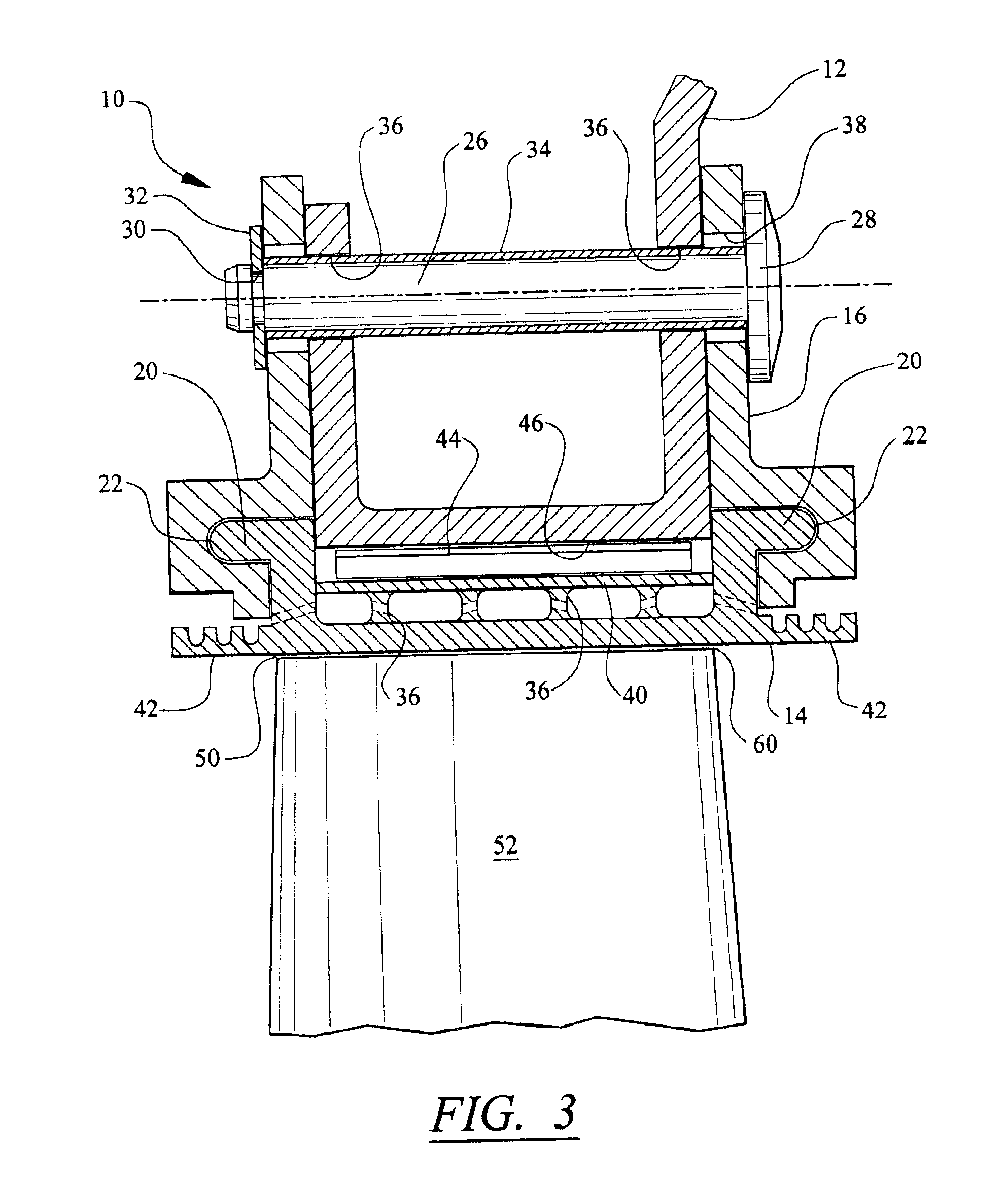
While the preferred embodiment of this invention is the turbine blade segment, one skilled in this art will also appreciate the fact that this invention has utility for use in a compressor assembly. In a dual spool gas turbine engine, for example, the blade segment of this invention can be used in the high pressure compressor and / or fan, low pressure compressor, first stage turbine and low stage turbine. In certain applications, the serpentine cooling that will be described herein below can be omitted and any other type of biasing or spring means other than the leaf spring can be utilized to urge the shroud toward the tips of the blades. While the preferred material is a low thermal expansion metal, as one skilled in this art will appreciate, a composite material can be substituted thereof The major criteria is that the material selected must exhibit a low thermal expansion coefficient and be capable of withstanding the hostile environment encountered in the turbine power plant tech...


PUM


Abstract

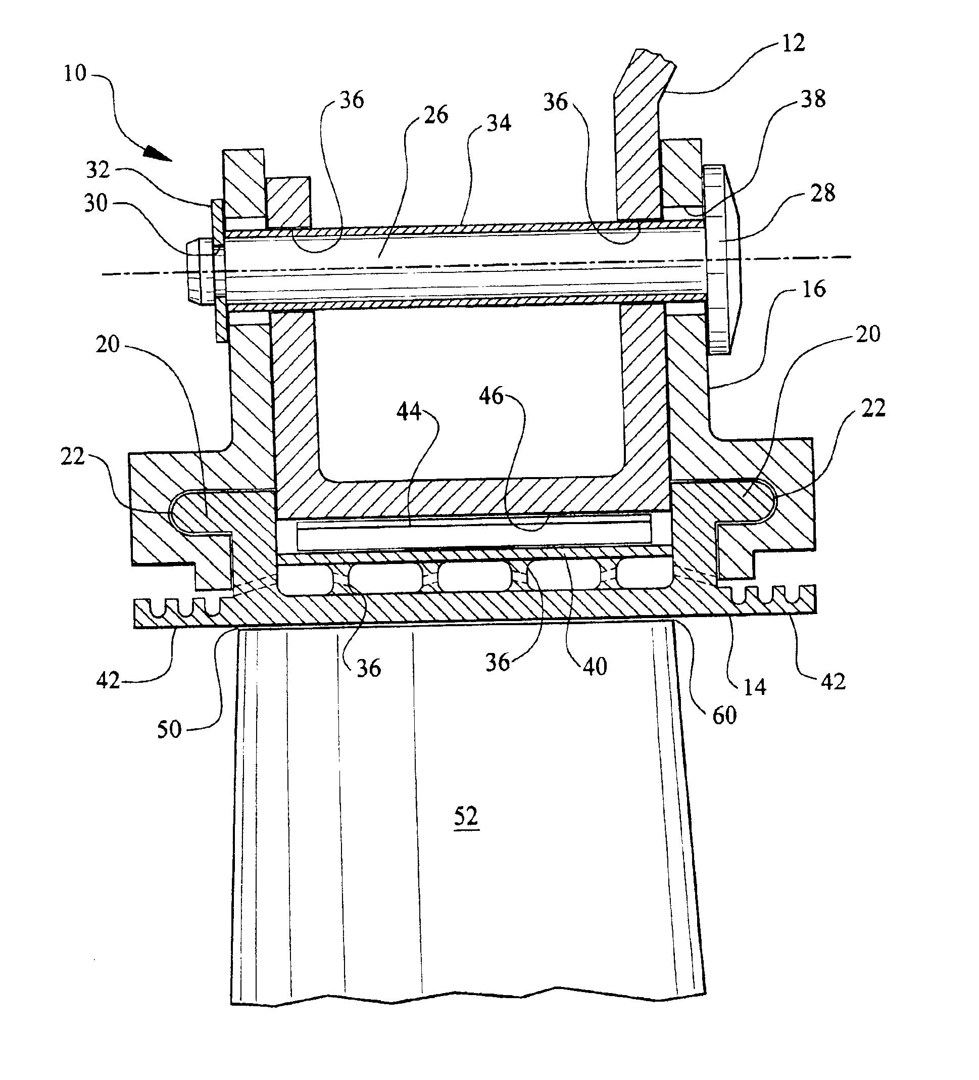
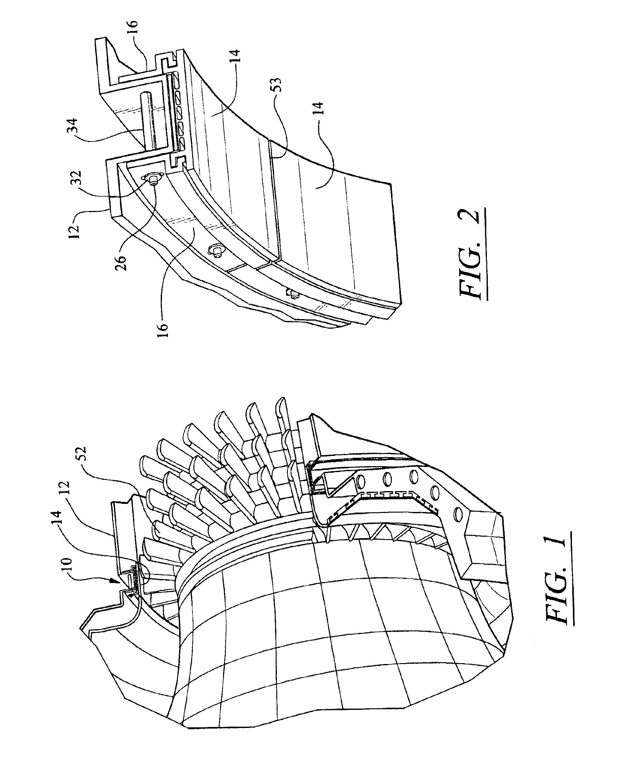
The clearance between the tips of the rotor blades and the segmented shroud of a gas turbine engine is controlled by a passive clearance control that includes a support ring made from a low thermal expansion material supporting a retainer for the blade outer air seal that is slidable relative thereto so that the segments expand circumferentially and move radially to match the rate of change slope of the rotor during expansion and contraction for all engine operations. A leaf spring between the support ring and outer air seal biases the outer air seal in the radial direction and maintains the desired radial position during steady state operation of the gas turbine engine.

Description

TECHNICAL FIELDThis invention relates to gas turbine engines and more particularly to the rotors and surrounding shrouds and means for reducing the clearance between the tips of the blades of the rotors and the shrouds and more particularly to a passive means of controlling this clearance.BACKGROUND OF THE INVENTIONAs one skilled in the gas turbine engine technology knows, there has been and continues to be a desire to reduce the clearance between the tips of the blades of the engine's rotors and the surrounding shrouds, sometimes referred to as blade outer air seal (BOAS) or blade segments, so as to improve the operating efficiency of the engine. Scientists and engineers have developed a number of systems for reducing the clearance with the aim of making it as tight as possible and a continuing effort is currently being made to make these clearances even tighter without adversely affecting the structural integrity of the component parts. Generically speaking, there are two types of...

Claims


Application Information

Patent Timeline
Patent Type & Authority Patents(United States)
IPC IPC(8): F01D11/08F01D11/18
CPCF01D11/18F05D2300/502Y02T50/672Y02T50/60
Inventor WILSON, JACK W.
Owner FLORIDA TURBINE TECH
Learn More