Shape cutting system

a cutting system and shape technology, applied in the field of shape rendering system, can solve the problems of error in desired marking or cutting, insufficient function in conjunction with templates, and inability to securely orient existing cutting devices in regard to angle with respect to materials,

Inactive Publication Date: 2005-04-12
ALTERRA HLDG
View PDF33 Cites 13 Cited by
  • Summary
  • Abstract
  • Description
  • Claims
  • Application Information

AI Technical Summary

Benefits of technology

The present invention provides a shape cutting system for cutting a material having a surface. The shape cutting system includes a cutting unit and at least one template. The cutting unit includes a frame, a blade adjustment assembly coupled to the frame, and a blade assembly coupled to the frame. The frame has a lower support surface. The blade assembly is positioned at least partially within the frame such that a longitudinal axis of the blade assembly is substantially perpendicular to the lower support surface of the frame. The blade assembly includes a blade retainer and a blade connected to the retainer which has a rigid collar. The blade assembly is rotatable about the longitudinal axis. The at least one template has first and second substantially flat surfaces, a periphery and at least one edge defining at least one opening. The frame of the cutting unit has a lower surface for contacting at least one of the first surface of the template and the material to be cut. The second surface of the template is configured for placement upon the material to be cut. The rigid collar of the retainer is configured to operatively engage either the periphery of the edge of the opening of the template. The engagement of the collar to the template enables the blade to cut a shape in the cutting material which assimilates the shape of at least a portion of the at least one of the periphery and the edge.

Problems solved by technology

Existing rendering or cutting devices are typically not securely orientated in regard to angle with respect to the material.
As a result, the angular orientation of the device with respect to the material to be cut (e.g., the blade of a cutting device) is often inadvertently changed causing an error in the desired marking or cutting.
Existing devices which do fix the angular orientation of the cutting device with respect to the material are typically configured for free-form cutting only and do not properly function in conjunction with templates.
Other devices which fix the angular orientation of the cutting device with the material to be cut are large, expensive devices which are often difficult to operate and to transport.
Further, existing cutting devices are typically formed of non-transparent material which partially obstructs the user's view of the material to be cut.
The bottom-load connection of the blade to the housing makes the blade susceptible to becoming dislodged from the housing during operation.
Existing cutting devices also typically do not include blade depth indication which increases the likelihood of blade depth mis-adjustment.
Existing cutting devices also typically do not accommodate spare blades or blade assemblies.
Those cutting devices, which have a rotatable or swivelable blade, are not typically configured for use with a template.
When not in operation, existing cutting devices often have exposed cutting blades which are susceptible to contact by the user.
Existing templates are not configured for effective operation with cutting devices, and in particular, with cutting devices wherein the housing and the blade assembly are maintained in a generally fixed orientation with respect to the template.
The periphery and the edges at the openings of existing templates often cause existing rotatable or swiveling blade assemblies to bind which can result in mis-cuts.
Also, existing nested templates produce incomplete shapes and require the user to undertake a secondary cutting or marking operation, typically without the aid of the template, to complete the cutting or marking of the desired shape.

Method used


Image

  • Shape cutting system
  • Shape cutting system
  • Shape cutting system

Examples


Embodiment Construction

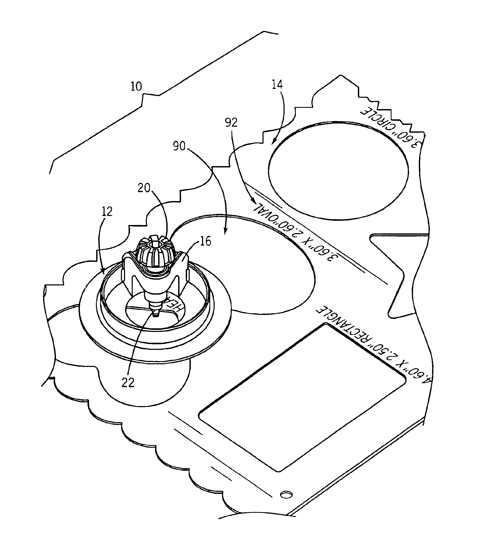
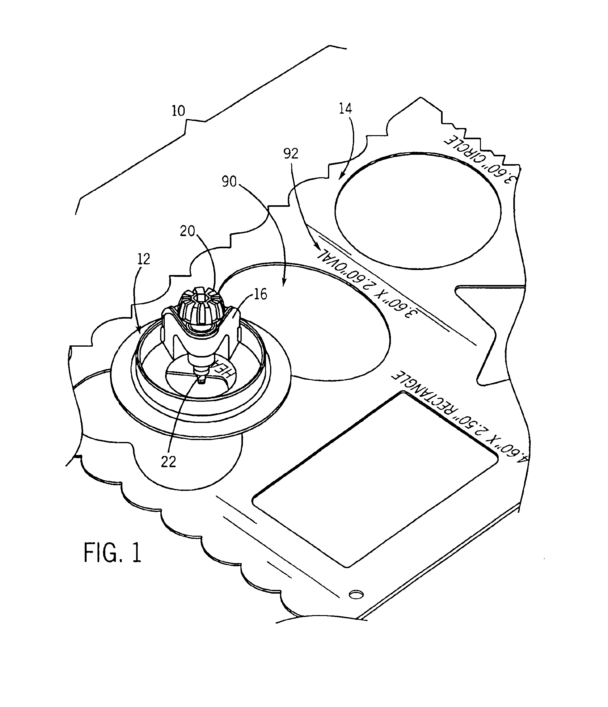
Referring to FIG. 1, a shape cutting system is indicated generally at 10. The shape cutting system 10 includes a cutting unit 12, at least one template 14 and a cutting mat 15 (see FIG. 5). The cutting unit 12 is a lightweight, handheld positionable assembly configured for operation with one of the templates 14 and for application directly onto a material to be cut without templates. The cutting unit 12 is also configured to cut material such as paper, card stock, photographs, and other related goods into desired shapes or patterns. The cutting unit 12 functions in at least two operating modes. In the first operating mode, a free-form or free-hand mode, the cutting unit 12 is placed directly upon the material to be cut and is translated preferably by a single hand of the user, in the desired direction across the material to perform free-form cutting. In the second mode of operation, the template cutting mode, the cutting unit 12 works in conjunction with at least one of the template...


PUM

PropertyMeasurementUnit
Pressureaaaaaaaaaa
Transparencyaaaaaaaaaa

Abstract

A shape cutting system for cutting a material having a surface. The shape cutting system includes a cutting unit and at least one template. The cutting unit includes a frame, a blade adjustment assembly and a blade assembly are coupled to the frame. The blade assembly is positioned at least partially within the frame such that a longitudinal axis of the blade assembly is substantially perpendicular to a lower support surface of the frame. The blade assembly includes a blade retainer and a blade connected to the retainer. A rigid collar of the retainer is configured to operatively engage at least one of a periphery and the edge of an opening of the template thereby enabling the blade to cut a shape in the cutting material which assimilates the shape of at least a portion of the at least one of the periphery and the edge.

Description

FIELD OF THE INVENTIONThe present invention relates generally to a shape rendering system. More particularly, the present invention relates to the field of marking devices, including cutting devices, and templates.BACKGROUND OF THE INVENTIONDevices for rendering marks upon materials such as paper, cardstock and photographs are generally well known. Such devices, including cutting devices, are typically configured for performing free-form marking or cutting. Many marking devices are also used in conjunction with a template for marking or cutting specific or predetermined shapes from a material. Cutting devices having an adjustable blade are also known and are typically used for cutting materials of varying thicknesses. Other cutting devices can include a swiveling blade which swivel or rotate about a longitudinal axis of the cutting device. Cutting devices typically are elongate members having housings which form a handle for grasping by a user during cutting. The housing usually con...

Claims


Application Information

Patent Timeline
IPC IPC(8): B26B29/06B26B29/00
CPCB26B29/06Y10T408/895Y10T83/7653Y10T83/7507Y10T83/875Y10T83/75
Inventor CARLSON, CHRISTOPHER R.SCHULZ, WILLIAM J.FOGHT, JAMIESON
Owner ALTERRA HLDG
Why Eureka
Try Eureka