
Inflatable support

a technology of inflatable support and support plate, which is applied in the direction of positive displacement liquid engine, mattress, sofa, etc., can solve the problems of system prone to the same problems and the ineffective static performance of the pressure pad, and achieve the effect of preventing deflation of the cells, reducing the size of the support plate, and improving the pressure reli

Inactive Publication Date: 2005-04-12
HUNTLEIGH TECH LTD
View PDF35 Cites 72 Cited by
  • Summary
  • Abstract
  • Description
  • Claims
  • Application Information

AI Technical Summary

Benefits of technology

According to the present invention, there is provided a pressure pad comprising at least two sets of inflatable cells; a fluid supply line to each set of cells; a pump arrangement to inflate each set of cells via the supply lines; a sensor, a separate supply line connected to the sensor for fluid to flow through the sensor to exhaust, the sensor located beneath the cells; and control means controlling the output of the pump to increase or decrease a supply of fluid to the cells in dependence on the rate of flow of fluid to the exhaust from the sensor. The invention eliminates the need for maximum compressor output at all times with separate pressure control and wasted compressor output. This has the advantage of increased compressor life and lower running costs.
Preferably, the supply of fluid through the sensor pad to exhaust vents into a space between the inflatable cells within the pressure pad, to provide a humidity gradient across the pad for greater patient comfort.
Preferably, all the inflatable segments are inflated to a first support pressure, the segments supporting the heels of a user lying upon or otherwise supported by the pad and maintained at the first support pressure, and the segments supporting at least a torso of the user further inflated and maintained at a second support pressure, the second support pressure higher than the first. Preferably, the cells supporting the heel and / or the head are of a smaller size for better pressure relief.
Preferably, the valves automatically close in the event of no power, for example a loss of power to at least one of the control means and the pump, thus preventing deflation of the cells and providing support for a user during power failure or during transport when power is not available.
Preferably, at least one segment of cells supporting the torso of a user is deflated separately to facilitate user entry or exit from the pressure pad. Preferably, the supply lines to the cells and sensor pad are located beneath the pressure pad to allow for easy exit by a user from the side of the pressure pad.
Preferably, each cell can be deflated individually to provide pressure relief to the different parts of the body supported thereon.

Problems solved by technology

Moreover, the static performance of the pressure pad is not as effective as the alternating performance as the optimum static pressure cannot be set.
The system is prone to the same problems as outlined above.

Method used


Image

  • Inflatable support
  • Inflatable support
  • Inflatable support

Examples


Embodiment Construction

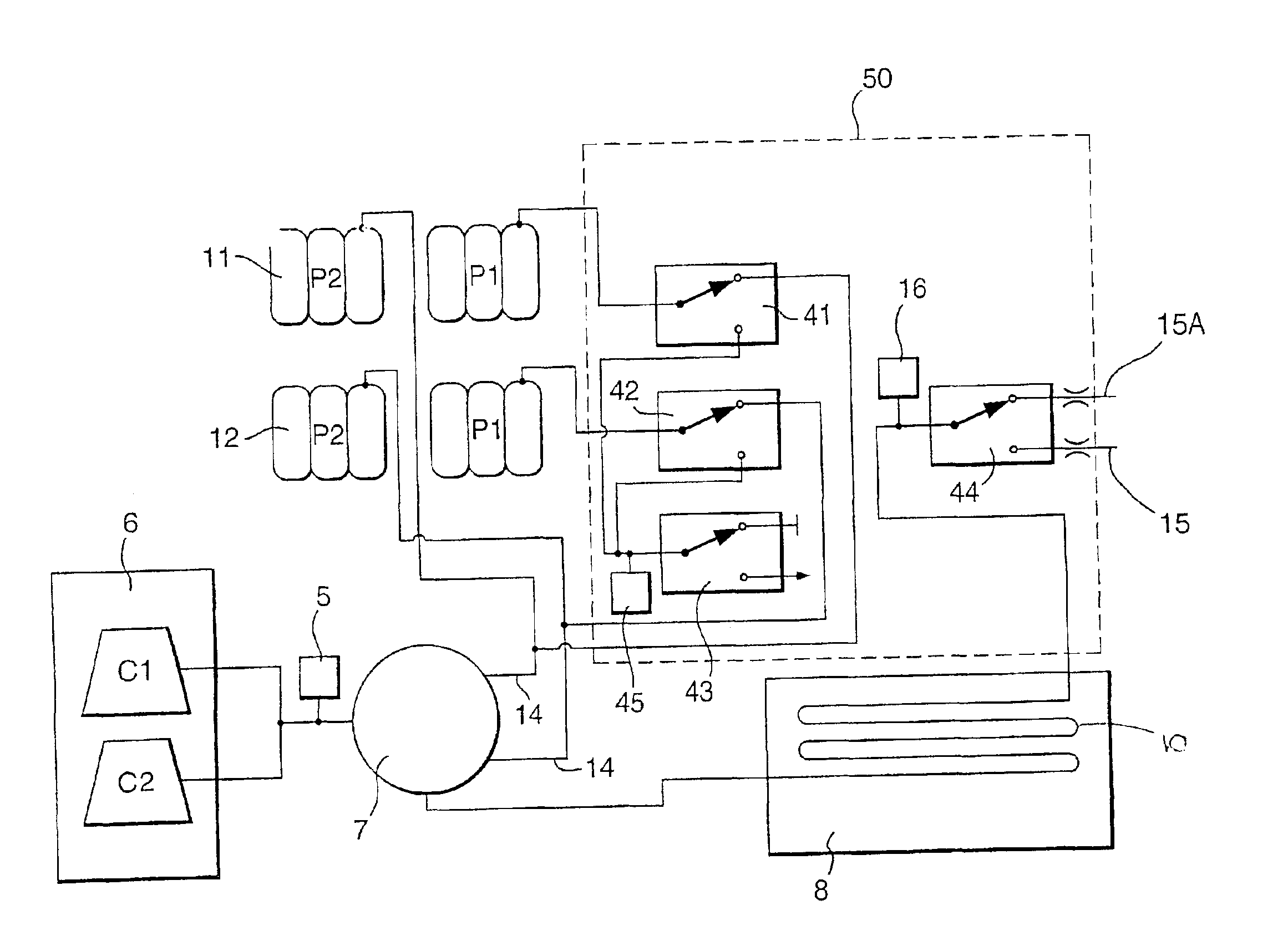
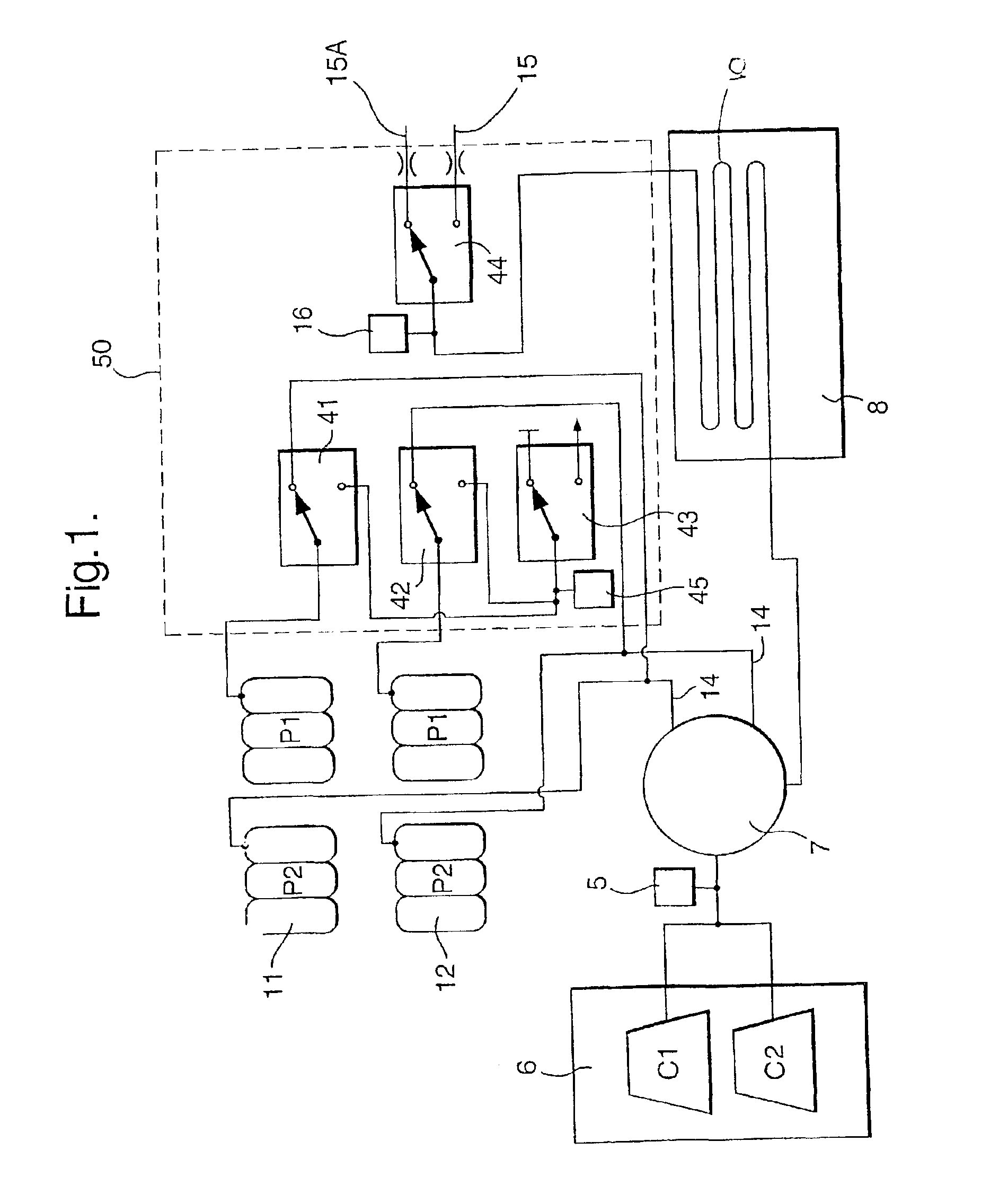
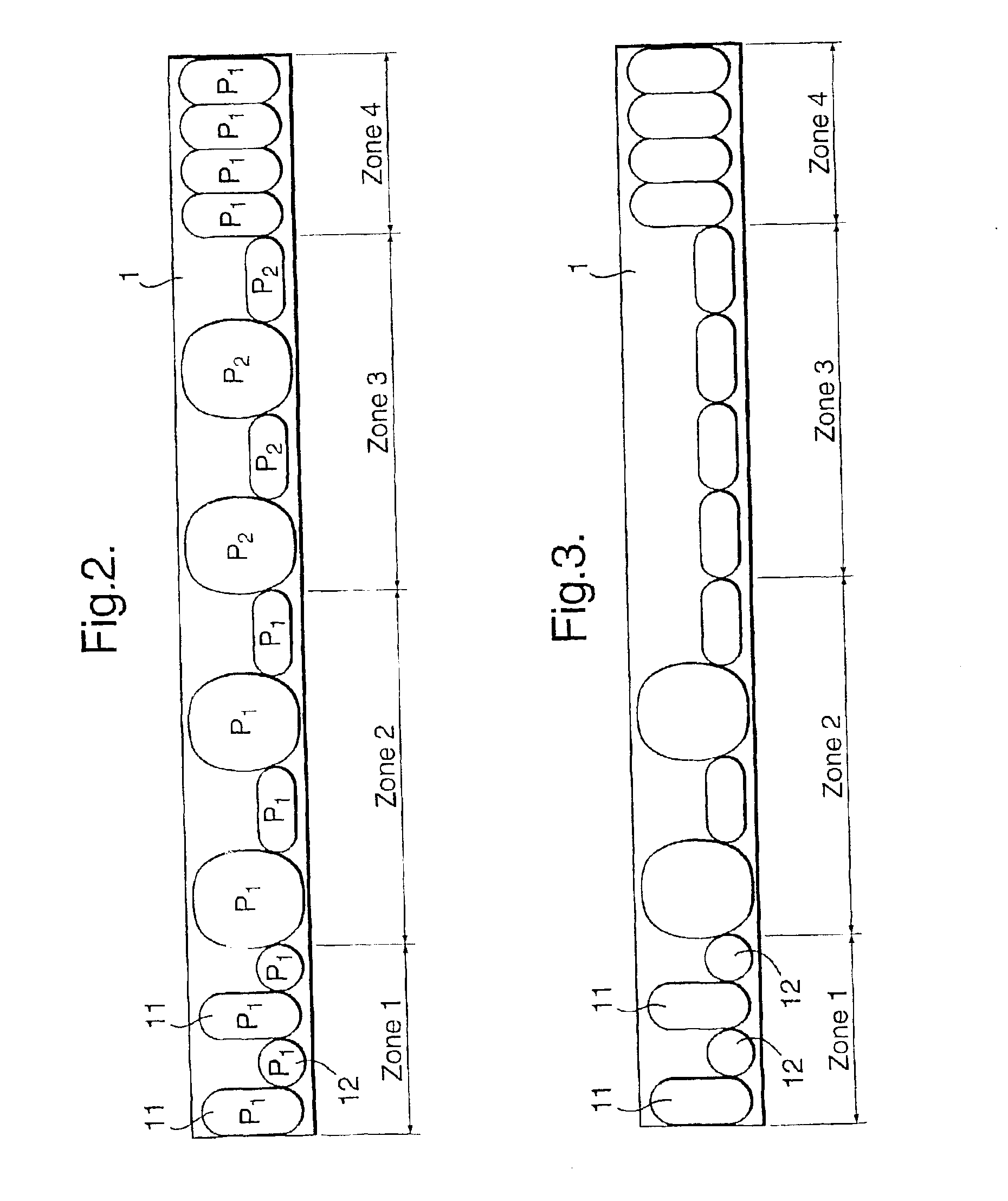
Referring to FIG. 1, an alternating pressure pad 1 (see also FIGS. 2, 3, 4) comprises a first set 11 and a second set 12 of alternately inflatable cells. Both sets of inflatable cells are supplied with air from a pump 6 via a rotary valve 7. A pair of air supply lines 14 lead from the rotary valve 7 to the pad.

A tube 10 of a sensor pad 8 is connected at one end to the output of the pump 6 and at the other end to a solenoid 44, pressure transducer 16 and two different exhaust flow restrictors 15 and 15a. The tube 10 comprises a portion which is positioned under the pad 1 to receive pressure exerted by a patient and to be compressible depending on the pressure applied.

The compressible portion of the tube 10 is, in this embodiment, a single compressible tube arranged in a convoluted path and formed as a sensor pad 8. The pad 8 may be formed of two polyurethane sheets welded together to define a single convoluted tube. In an alternative embodiment (not shown), the two sheets may he weld...


PUM


Abstract

A pressure pad has two sets of cells with a sensor pad positioned under the pad. During inflation, part of the flow goes to the sensor pad to exhaust and the rest fills the cells. Any change in patient position / weight causing a change in airflow in tube will alter the differential pressure measured at a pressure transducer. Based on this feedback a microprocessor directly controls the power level to the pump, thus adjusting the airflow to the cells to prevent bottoming or to rung at a minimum pressure. The pressure pad is segmented into a heel section, upper leg section, torso section, and a head section. The heel, head, and upper leg sections are maintained at a lower pressure, and the torso section at a higher pressure. A control module to control the flow in the segments is provided inside the pressure pad. The pressure pad can be an alternating or static pad.

Description

The present invention relates to a pressure controlled inflatable pad apparatus, in particular, a pressure controlled alternating or static inflatable pressure pad apparatus.BACKGROUND OF THE INVENTIONAlternating pressure pads are well known for the prevention and management of decubitus ulcers in bedridden patients. The formation of decubitus ulcers, commonly known as bedsores, results from, amongst other things, the pressure applied to certain portions of the skin of a bedridden patient.Alternating pressure pads generally comprise two sets of alternately inflatable cells; the duration of the inflation and deflation cycles may last from under two minutes for a gentle massaging effect to over twenty minutes.A high air pressure in the pads may be needed to support the bony protuberances of a patient and to ensure that the patient is lifted sufficiently away from deflated cells of the pad so that adequate pressure relief is provided. A low air pressure, however, is desirable since it ...

Claims


Application Information

Patent Timeline
IPC IPC(8): A61G7/057A47C27/10A61G7/05A61H7/00F04B49/06
CPCA61G7/05776
Inventor CHAPMAN, PAUL WILLIAMHARBIGE, JANEKEMP, DANIELSMITH, ANTHONY GEORGE
Owner HUNTLEIGH TECH LTD
Learn More