
Compact particle sensor

a sensor and compact technology, applied in the field of sensors, can solve the problems of not being able to adapt to changing environmental conditions and responding appropriately to different particle reflectivities

Inactive Publication Date: 2005-04-05
GENTEX CORP
View PDF63 Cites 46 Cited by
  • Summary
  • Abstract
  • Description
  • Claims
  • Application Information

AI Technical Summary

Benefits of technology

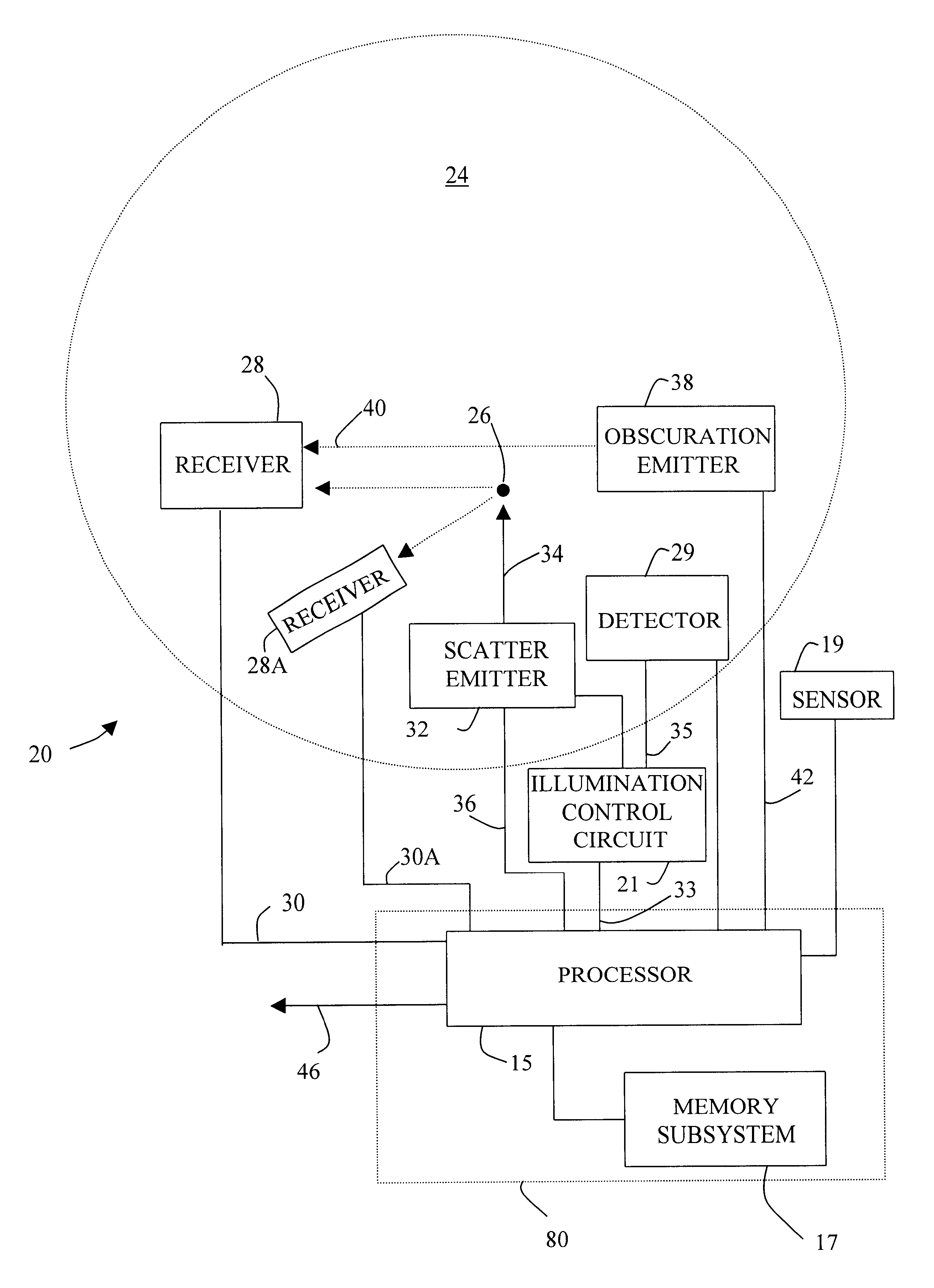
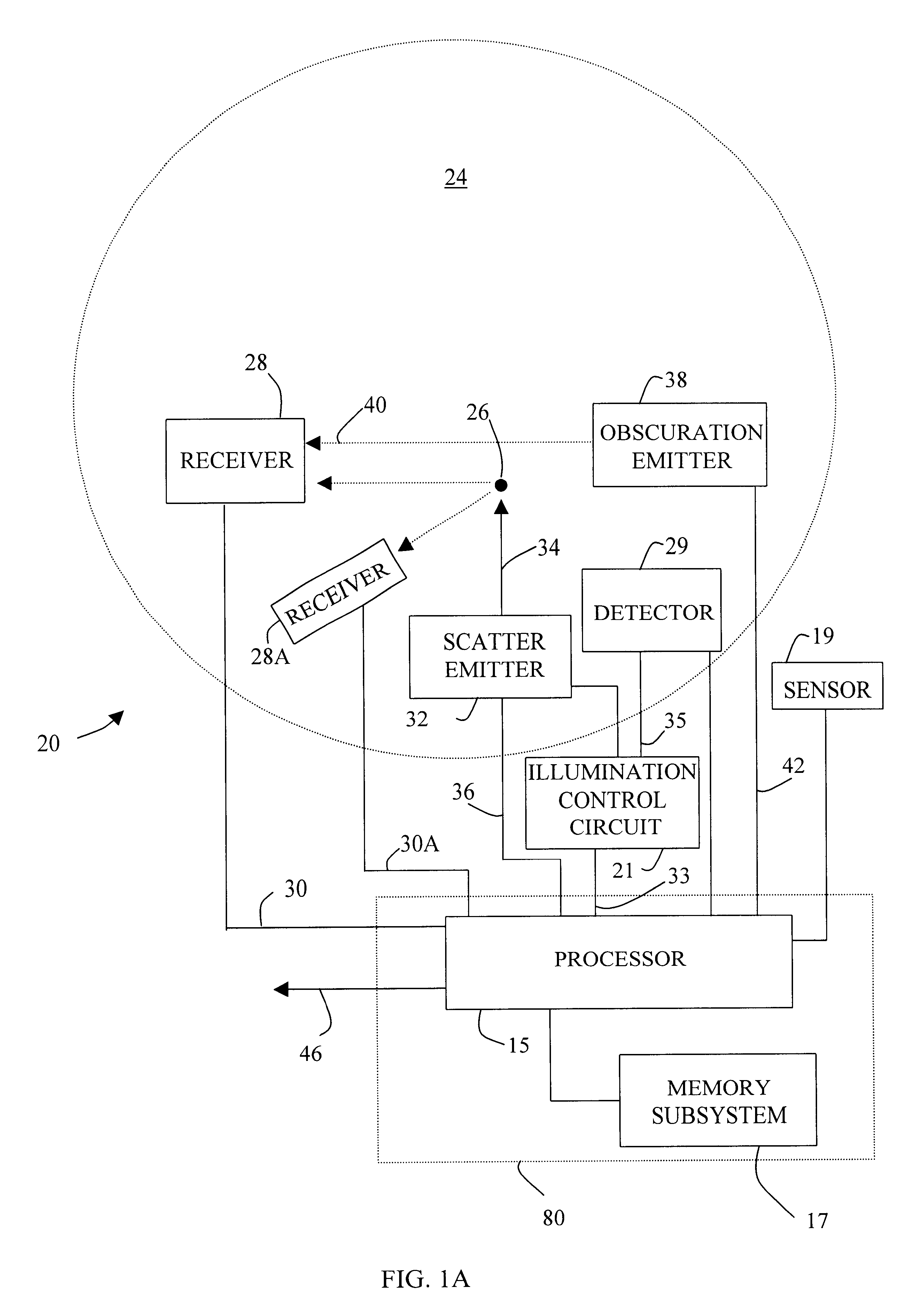
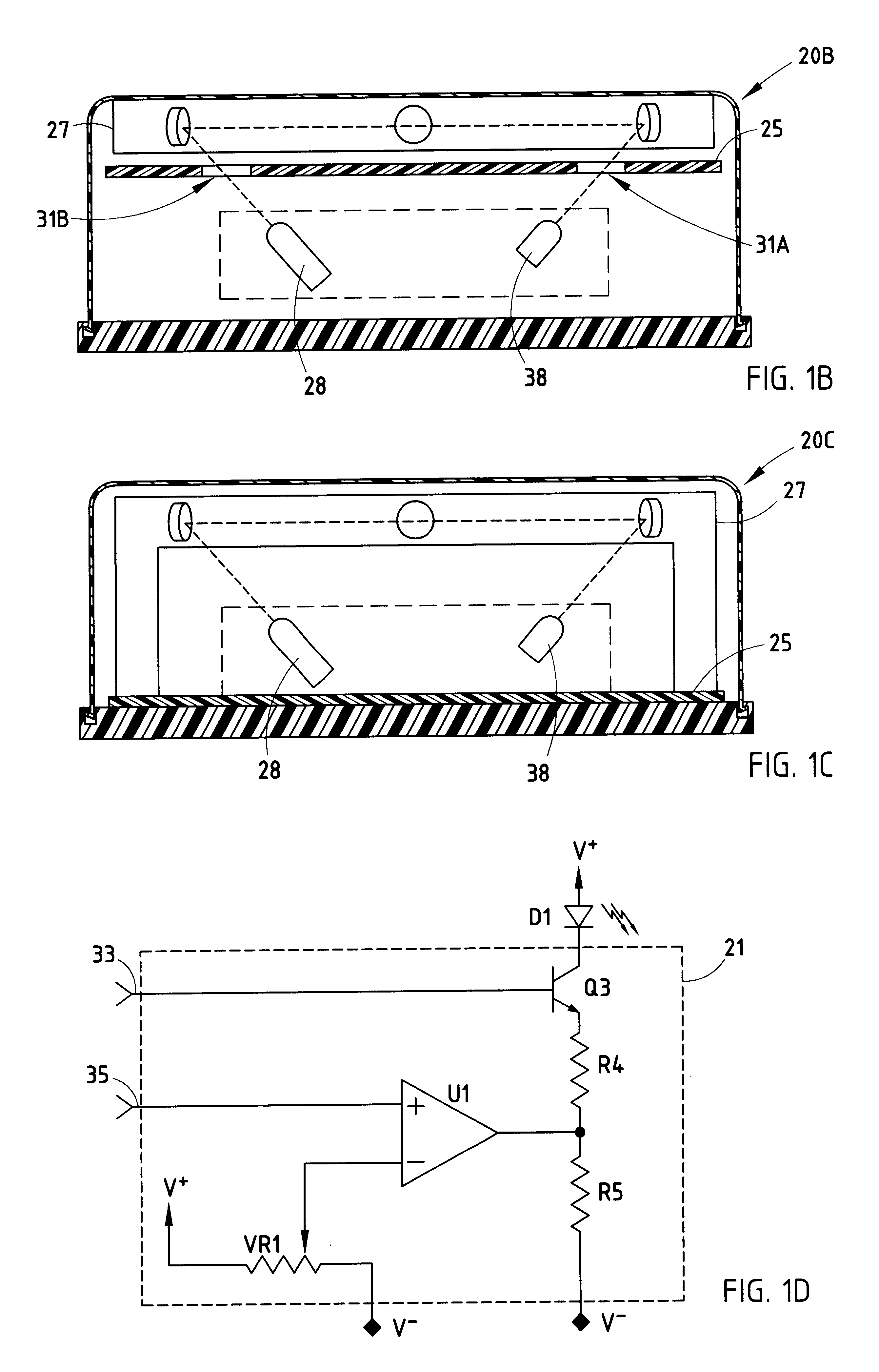
The present invention is a small device that can detect suspended particles. It has a housing with an opening for particles and a light source inside. The light is directed by optical elements to a receiver. This device is designed to prevent outside light from entering the chamber where the particles are tested. Its technical effect is to provide a reliable and accurate method for detecting particles in a compact and efficient way.

Problems solved by technology

Thus, there has been a tradeoff between sensitivity and compactness.
Further, such sensors have implemented fixed alarm thresholds and, as such, have generally been incapable of adapting to changing environmental conditions and responding appropriately to different particle reflectivities.

Method used


Image

  • Compact particle sensor
  • Compact particle sensor
  • Compact particle sensor

Examples


Embodiment Construction

General Considerations

A weakness of many contemporary smoke detectors is their reliance on a single measured characteristic of smoke particles to indicate the presence, or lack, of smoke in a test chamber of the smoke detector. This is generally true for both ionic and optical methods of detecting smoke. In the case of the optical scatter technique of detection, the characteristic of concern is the ability of the smoke to reflect light. Although the wavelengths of light emanating from a light source may be controlled to enhance the desired response, the reflected light provides a single indicator. In the case of the optical obscuration technique, the measured characteristic of the smoke is its ability to attenuate light emanating from a light source. Again, the wavelength of light may be chosen to enhance this effect.

The ability of smoke to either reflect or attenuate light is generally determined by more than just the density of the particles suspended in the measurement medium, us...


PUM


Abstract

A compact particle sensor for fdetecting suspended particles includes a housing, a light source, a light receiver and a plurality of optical elements. The housing provides a test chamber and includes at least one opening for admitting particles into the test chamber, while simultaneously substantially preventing outside light from entering the test chamber. The light source is positioned for supplying a light beam within the test chamber. The plurality of optical elements are positioned to direct the light beam from the light source to the receiver, which is positioned to receive the light beam supplied by the light source.

Description

BACKGROUND OF THE INVENTIONThe present invention is generally directed to a sensor for detecting suspended particles and, more particularly, to a compact particle sensor.Obscuration sensors have been utilized as smoke detectors in closed structures such as, houses, factories, offices, shops, ships and aircraft to provide an early indication of fire. Historically, obscuration sensors have included an obscuration emitter and a light receiver spaced at a substantial distance, such as one meter or across a room, to achieve a desired sensitivity. In general, the longer the light beam path, the more likely a smoke particle will interrupt the beam and, hence, the more sensitive the obscuration sensor. Thus, there has been a tradeoff between sensitivity and compactness.Obscuration sensors have normally been utilized to detect black smoke with particles in the range of 0.05 to 0.5 microns, which are generally produced by rapidly accelerating fires. Traditionally, obscuration or direct sensor...

Claims


Application Information

Patent Timeline
Patent Type & Authority Patents(United States)
IPC IPC(8): G08B29/00G08B29/04G08B17/107G08B17/103G08B29/24
CPCG08B17/107G08B29/24G08B29/043G08B17/125G08B17/113
Inventor KADWELL, BRIAN J.PATTOK, GREG R.
Owner GENTEX CORP
Learn More