
Method and system for accelerated imaging using parallel MRI

a parallel imaging and accelerated imaging technology, applied in the field of parallel imaging, can solve the problems of limiting the speed with which the k-space matrix may be filled, the application of a field gradient does not allow two-dimensional spatial encoding, and the frequency-encoding gradient alone cannot make it possible to discern signals originating,

Inactive Publication Date: 2005-04-05
GENERAL ELECTRIC CO
View PDF19 Cites 19 Cited by
  • Summary
  • Abstract
  • Description
  • Claims
  • Application Information

AI Technical Summary

Problems solved by technology

However, the application of a field gradient does not allow for two-dimensional spatial encoding, since all nuclei at a given left-to-right position experience the same field strength, and hence emit signals of the same frequency.
Accordingly, the application of a frequency-encoding gradient, by itself, does not make it possible to discern signals originating from the top versus signals originating from the bottom of the person at a given left-to-right position.
Although many improvements have been made in this general area, the speed with which the k-space matrix may be filled is limited.
In either case, the reconstructed images tend to suffer from incomplete removal of aliasing artifacts, especially for large speedup factors.

Method used


Image

  • Method and system for accelerated imaging using parallel MRI
  • Method and system for accelerated imaging using parallel MRI
  • Method and system for accelerated imaging using parallel MRI

Examples


Embodiment Construction

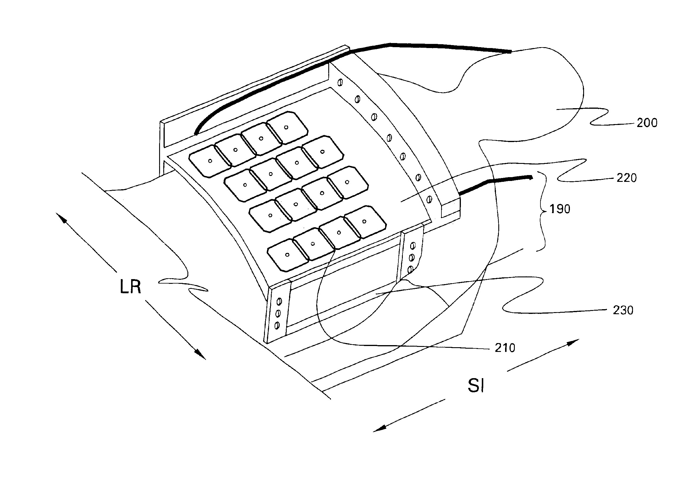
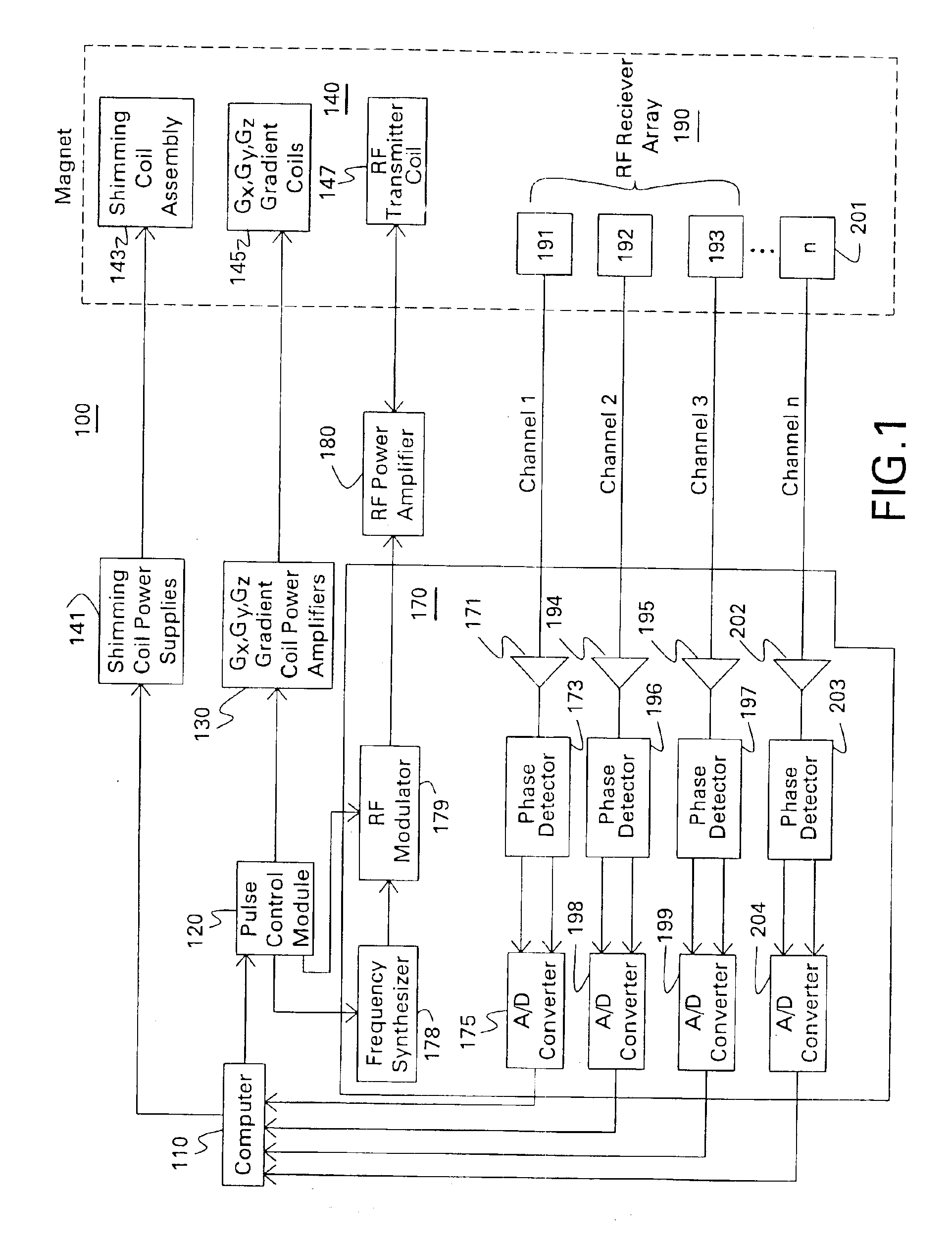
[0020]FIG. 1 is an exemplary embodiment of a magnetic resonance imaging (MRI) system 100. MRI system 100 includes a computer 110, which controls gradient coil power amplifiers 130 through a pulse control module 120. The pulse control module 120 and the gradient amplifiers 130 together produce the proper gradient waveforms Gx, Gy, and Gz, for either a spin echo, a gradient recalled echo pulse sequence, a fast spin echo, or other type of well-known pulse sequences. The gradient waveforms are connected to gradient coils 145, which are positioned around the bore of an MR magnet assembly 140 so that gradients Gx, Gy, and Gz are impressed along their respective axes on the polarizing magnetic field B0 from magnet assembly 140.

[0021]The pulse control module 120 also controls a radio frequency (RF) synthesizer 178 that is part of RF transceiver system 170, portions of which are enclosed by bold line block. The pulse control module 120 also controls an RF modulator 179, which modulates the o...


PUM


Abstract

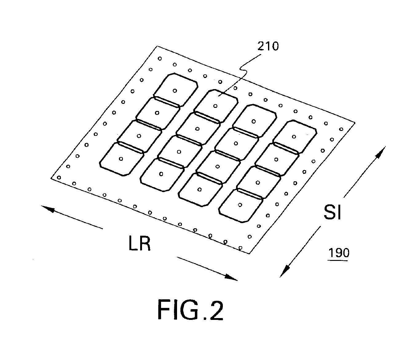
A method of and system for parallel imaging using a Magnetic Resonance Imaging (MRI) system is provided. The method comprises acquiring a plurality of magnetic resonance (MR) signals from a receiver coil array placed about a subject in the MRI system, where the receiver coil array has a plurality of receiver elements arranged in rows and, during application of a readout gradient in a frequency encoding direction, shifting receiver frequencies by a selectable amount for each row of the array in order to shift a limited field of view (FOV) in the frequency encoding direction.

Description

STATEMENT REGARDING FEDERALLY SPONSORED RESEARCH & DEVELOPMENT[0002]The U.S. Government may have certain rights in this invention pursuant to grant RO1 RR15396-01A1 awarded by the National Institutes of Health (NIH).BACKGROUND OF THE INVENTION[0003]The invention relates generally to Magnetic Resonance Imaging (MRI) systems and more specifically to a method and apparatus for parallel imaging in the frequency-encoding direction using MRI systems.[0004]MRI is a well-known imaging technique. A conventional MRI device establishes a homogenous magnetic field, for example, along an axis of a person's body that is to undergo MRI. This homogeneous magnetic field conditions the interior of the person's body for imaging by aligning the nuclear spins (in atoms and molecules forming the body tissue) along the axis of the magnetic field. If the orientation of the nuclear spins is perturbed out of alignment with the magnetic field, the nuclei attempt to realign their spins with the axis of the mag...

Claims


Application Information

Patent Timeline
Patent Type & Authority Patents(United States)
IPC IPC(8): A61B5/055G01R33/34G01R33/3415G01R33/54G01R33/561
CPCG01R33/3415G01R33/5611
Inventor HARDY, CHRISTOPHER JUDSONDUMOULIN, CHARLES LUCIAN
Owner GENERAL ELECTRIC CO
Learn More