Clamp device

Inactive Publication Date: 2005-04-05
CLECO NEW ZEALAND
View PDF11 Cites 3 Cited by
  • Summary
  • Abstract
  • Description
  • Claims
  • Application Information

AI Technical Summary

Problems solved by technology

The bar was prone to slipping when in use.

Method used


Image

  • Clamp device
  • Clamp device
  • Clamp device

Examples


first embodiment

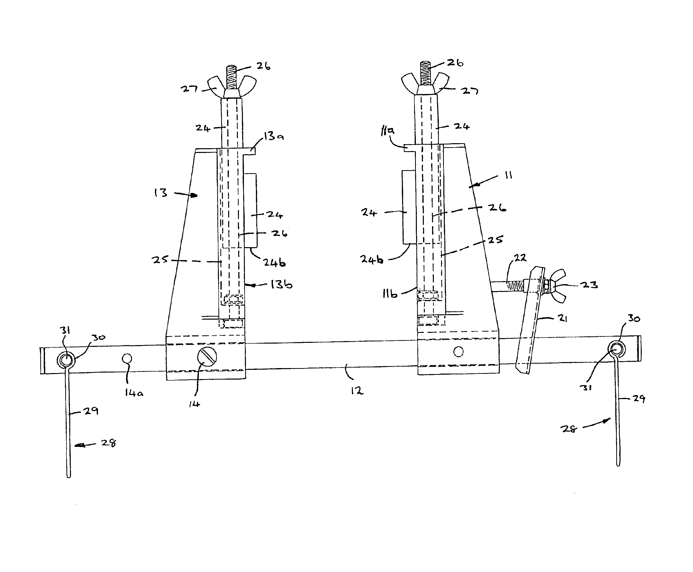
The clamp device 10 as seen in its entirety in FIG. 1 is principally comprised of a first engagement element 11, which is slidingly located upon a tubular cross member or bar 12. A second engagement element 13 is fixed to the bar12 by a rivet or like fastener 14.

Each engagement element 11, 13 includes a flange 11a, 13a for location over the top edge surface of an architrave or like edge of opposite sides of a conventional doorway (not illustrated).

When the second engagement element 13 is in place with engagement surface 24a of flange 13a thereof abutting a face surface of a top of a door frame and the flange 13a hooked over the door frame / architrave, first engagement element 11 may be slid along bar 12 so that its engagement surface 11a can abut the other face surface of door frame / architrave from the other side of the doorway. The flange 11a will similarly hook over the top frame / architrave on said other side of the doorway.

To keep the first and second engagement elements in clamp...

second embodiment

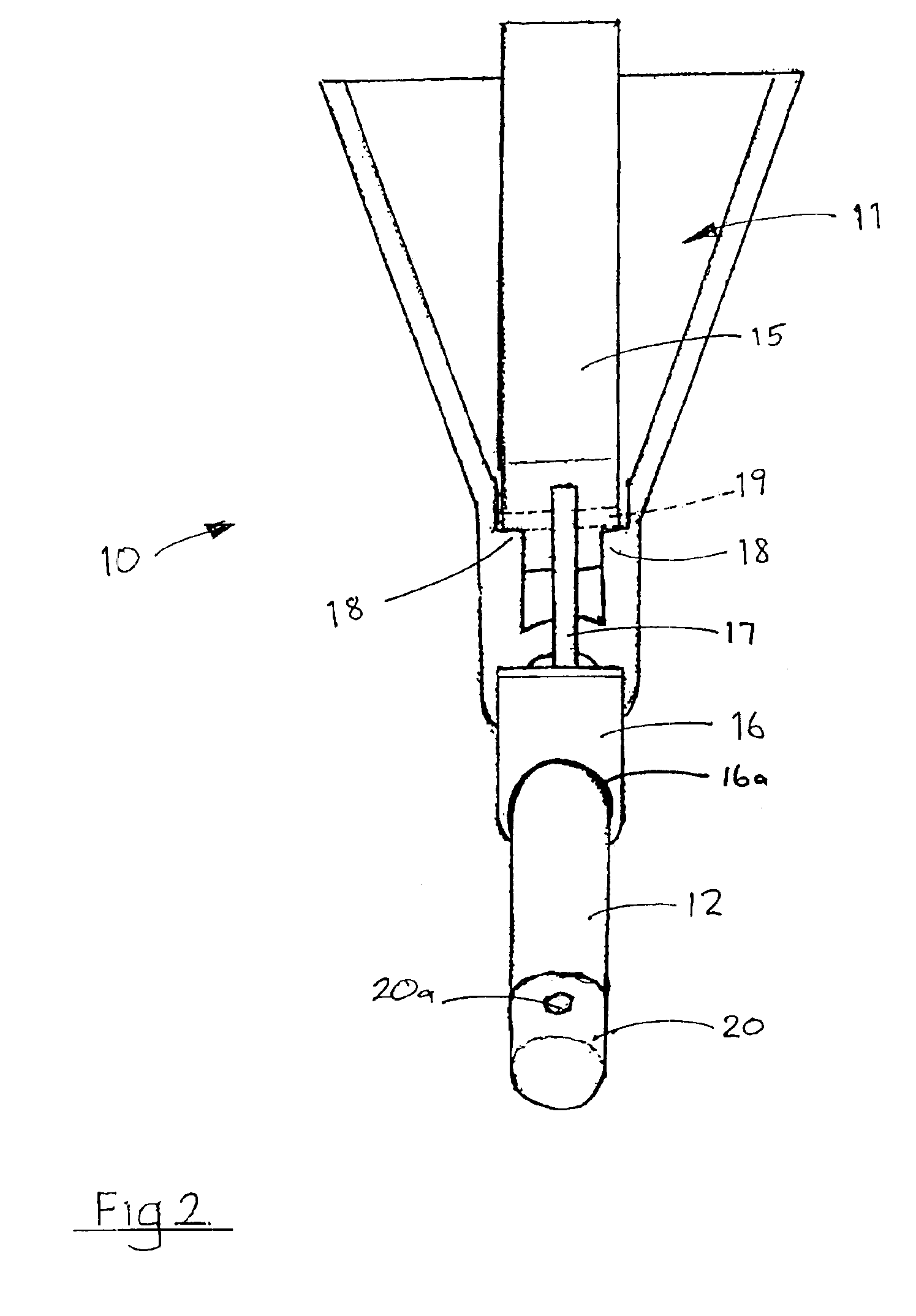
FIGS. 3 to 5 illustrate the clamp device according to the invention.

It has been observed that the forward and reverse action of a child's swing can cause ‘crabbing’ on a clamp bracket that only applies horizontal pressure (as in first embodiment) to the door frame. Therefore, the second embodiment provides a vertical tensioner element in addition to the horizontal clamping action.

Horizontal pressure is secured in a simpler arrangement to that of the first embodiment, namely a grab plate 21 mounted about bar 12 (which in the second embodiment has a square cross section). Grab plate 21 is tensioned to first engagement means 11 by a threaded element 22 embedded or otherwise held in engagement means 11. A wingnut 23 or similar applies pressure to the upper end of plate 21 that in turn locks it to bar 12.

Thus, as shown the threaded element 22 can be a shaft which engages at one end with the first engagement element 11. Shaft 22 is free to rotate relative to engagement. The shaft 22 is th...


PUM


Abstract

A clamp device which is intended for clamping to the top of a door frame so that e.g. a swing can be suspended therefrom. The clamp device includes an elongate bar member 12. Slidably mounted on the bar 12 is a first engagement element 11 and a second engagement element 13. In use the shoulders 11a, 13a of the engagement elements 11, 13 hook over the top of the architrave of the door frame and the engagement elements 11, 13 clamp the door frame therebetween. The engagement element 13 is fixed in place on the bar 12 and the engagement element 11 is adjustable but lockable in the clamping position by a grab plate 21 engaged with the first engagement 11 by adjustment shaft 22. Mountings 28 are provided at each end of the bar 12 for attachment of the suspension cords of e.g. a swing.

Description

BACKGROUND OF THE INVENTIONThe present invention relates to a clamp device, more particularly a clamp device suitable for suspending a child's swing from a doorway in a building.The clamp device of the present invention has been developed for use with a swing such as that described by International Patent Application number PCT / NZ94 / 00058. This particular swing includes four cord elements from which the swing hangs. The cords must be fixed to a suitably stable structure such as an outdoor frame means.An investigation conducted to determine whether an indoor swing arrangement existed revealed only one product. This design incorporated an expanding bar fitted across an entire doorway for use with a conventional swing (which has only two suspended cords with the swing positioned therebetween). The bar was prone to slipping when in use.Another related product is a ‘baby bouncer’ type product which uses an elastic or spring biased harness to allow a baby to ‘jump’ in an up and down movem...

Claims


Application Information

Patent Timeline
IPC IPC(8): F16B2/02F16B2/10A63B21/16A63B21/00F16B2/24F16B2/20
CPCF16B2/10A63B21/1636F16B2/246A63B2208/12
Inventor PORTEOUS, DAVID LESLIE
Owner CLECO NEW ZEALAND
Why Eureka
Try Eureka