
Solenoid valve comprising a plug-in/rotative connection

a solenoid valve and plug-in technology, applied in the field of sole, can solve the problems of stop ring, tendency to wear, and considerable wear, and achieve the effect of improving guidance precision

Inactive Publication Date: 2005-04-05
ROBERT BOSCH GMBH
View PDF6 Cites 50 Cited by
  • Summary
  • Abstract
  • Description
  • Claims
  • Application Information

AI Technical Summary

Benefits of technology

The present invention provides a design approach for an armature group used in a solenoid valve that is simple and sturdy. The components of the armature group can be precisely adjusted with respect to one another without the need for special tools. The design allows for easy and reliable joining of multi-part armatures, ensuring they remain in the desired position. The design also prevents twisting of the components and ensures a trouble-free operation over a long period of time. Additionally, the design allows for the secure and reliable joining of armature plates and armature pins, eliminating the need for additional locking elements. Overall, the design approach provides a more efficient and reliable solution for the assembly of armature groups in solenoid valves.

Problems solved by technology

The stop ring is designed in the form of an open retaining disk and has a tendency to wear.
Considerable signs of wear may occur, which, on the one hand, may lead to play developing between the armature pin and the armature plate and, on the other hand, to the complete destruction of the retaining disk.
Even only play developing between the armature pin and the armature plate adversely influences the volume tolerances in the injection, thereby no longer providing, in particular, a repeat accuracy in injections of the most minuscule quantities implemented in rapid succession.

Method used


Image

  • Solenoid valve comprising a plug-in/rotative connection
  • Solenoid valve comprising a plug-in/rotative connection
  • Solenoid valve comprising a plug-in/rotative connection

Examples


Embodiment Construction

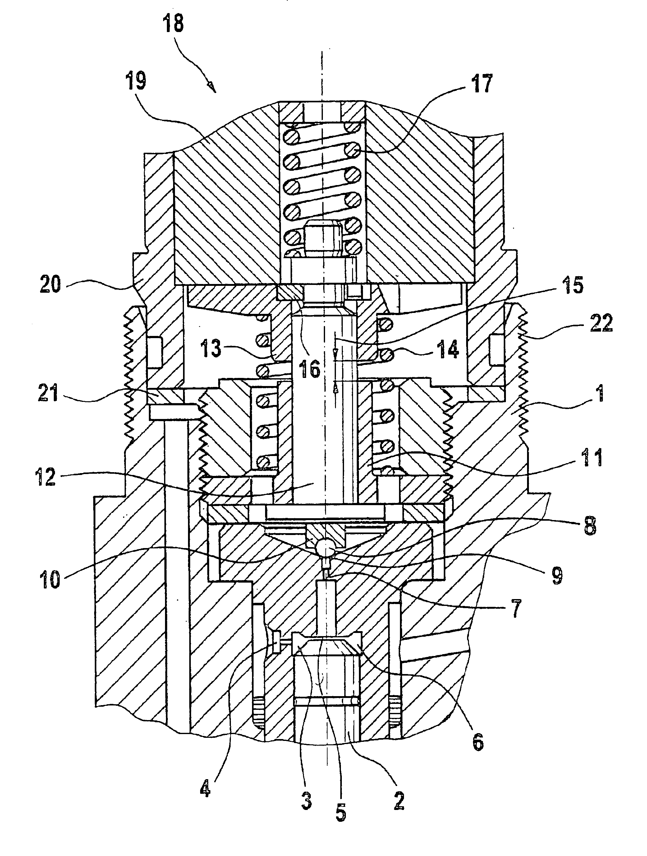
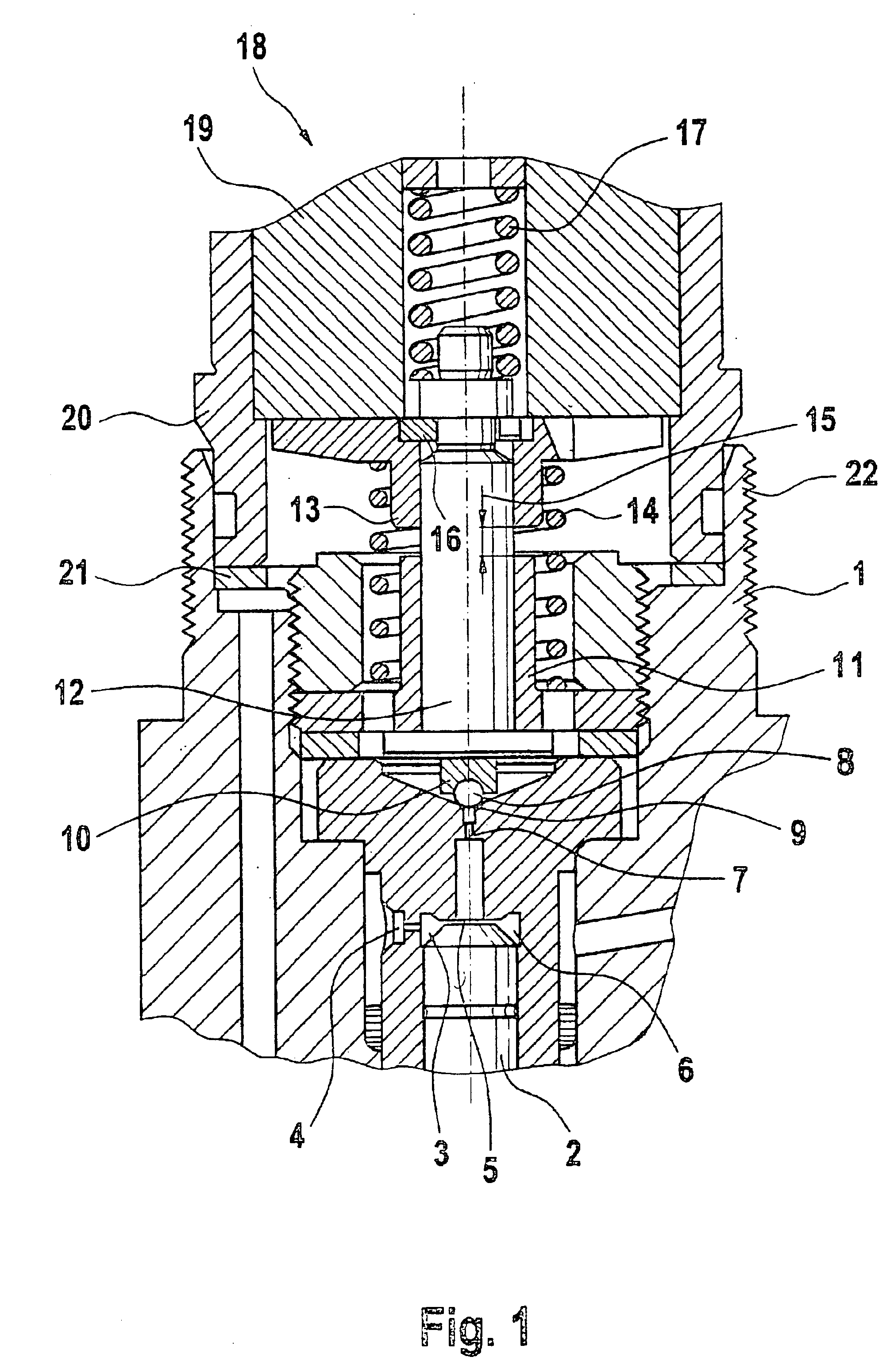
FIG. 1 shows an armature group having a two-piece design in which the armature plate and armature pin are provided with a retaining disk.

From the drawing according to FIG. 1 it may be inferred that a nozzle needle / tappet system 2 is accommodated in a control chamber 3 provided in injector body 1 of a fuel injector. Via an intake throttle 4, control chamber 3 is acted upon with a control volume, and is able to be biased via a discharge throttle 7 which relieves the pressure in control chamber 3 and may be activated by a closing member 8. An end face of nozzle needle / tappet system 2 projects into control chamber 3 enclosed by a boundary wall 6. Depending on the pressurization or the pressure relief of control chamber 3, nozzle needle / tappet system 2 projecting into control chamber 3 by its end face 5 is imparted with a vertical movement within injector body 1 during which injection orifices (not shown here) of the fuel injector at the combustion chamber of the internal combustion engi...


PUM


Abstract

A solenoid valve for a fuel injector for injecting fuel into the combustion chamber of an internal combustion engine having an injector body which includes an electromagnet. An armature group of the solenoid valve may be actuated by this electromagnet to relieve the pressure in a control chamber, so that a nozzle needle / tappet assembly in the injector body implements an opening / closing movement. The armature group includes a first and a second armature part. The first armature part and the second armature part are joined to one another by an insert-and-twist connection, one of the armature parts being enclosed by an armature guide which includes anti-rotation elements.

Description

FIELD OF THE INVENTIONSolenoid valves may be used in fuel-injection systems to actuate the fuel injectors. For this purpose, the solenoid valves include an electromagnet set into the injector body, which cooperates with an armature group having an armature pin and armature plate. The armature pin is designed such that it accommodates a closing member, which closes or releases an outlet of a control chamber actuating the nozzle needle of the fuel injector. To obtain a rapidly responding and precise lift movement of the armature group when the electromagnet is energized, a reliable and play-free connection of the armature plate and armature pin is required in the case of two-piece armature groups, or of the armature-guide sleeve and the armature pin in the case of a one-piece armature.BACKGROUND INFORMATIONGerman Published Patent Application No. 196 50 865 relates to a solenoid valve whose armature has a plurality of parts. The armature includes an armature plate and an armature pin, ...

Claims


Application Information

Patent Timeline
Patent Type & Authority Patents(United States)
IPC IPC(8): F02M59/00F02M59/46F02M47/02F02M47/00F02M51/06
CPCF02M47/027F02M63/0015F02M2547/003F02M2200/306F02M61/04
Inventor HANNEKE, JUERGENGAUDL, ANDREASANTHONY, GEORGE
Owner ROBERT BOSCH GMBH
Learn More