
Method and apparatus for detecting a stationary dither code

a technology of dithering code and code, applied in the field of data communication systems, can solve the problems of difficult acquisition, difficult acquisition, unwieldy receiver, etc., and achieve the effect of reducing the cost of acquisition

Inactive Publication Date: 2005-03-29
EXCELIS INC
View PDF3 Cites 3 Cited by
  • Summary
  • Abstract
  • Description
  • Claims
  • Application Information

AI Technical Summary

Benefits of technology

[0014]Therefore, in light of the above, and for other reasons that become apparent when the invention is fully described, an object of the pre

Problems solved by technology

However, because the P code is so long it is difficult for a receiver to determine its phase and therefore is difficult to acquire.
But this would require an expensive, complex and unwieldy receiver.
Even with a very accurate and stable clock frequency, there is the problem of initially setting the correct time of day.
Theoretically a receiver could include enough correlators to test each phase of the P code simultaneously to detect its phase, but in practice that solution would not be feasible because of the extremely large number of correlators required due to the length of the P code.
A receiver also, theoretically, could use a practical number of correlators and test the possible phases of the P code sequentially, however, that would take a long time due to the length of the P code.
However, the C / A code can provide timing only within one millisecond interval, because one such interval cannot be distinguished from another, and thus, by itself, cannot resolve all of the time uncertainty, which typically is a few seconds.
Accordingly, conventional spread-spectrum receivers, such as GPS receivers, suffer from the problems described above and are unable to detect a long code quickly and inexpensively without the aid of a second timing signal.

Method used


Image

  • Method and apparatus for detecting a stationary dither code
  • Method and apparatus for detecting a stationary dither code
  • Method and apparatus for detecting a stationary dither code

Examples


Embodiment Construction

enerator.

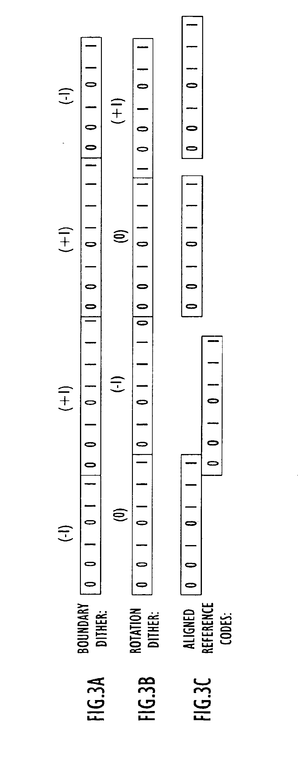
[0027]FIG. 3A shows an example boundary dither code.

[0028]FIG. 3B shows an example rotation dither code.

[0029]FIG. 3C shows alignments of a reference code with the boundary dither and rotation dither codes shown in FIGS. 3A and 3B that a receiver might use to detect either of the dither codes shown in FIGS. 3A and 3B.

[0030]FIG. 4 is a block diagram of a receiver according to one embodiment of the invention.

[0031]FIG. 5A is a block diagram of the maximum likelihood decoder shown in FIG. 4.

[0032]FIG. 5B is a block diagram of the maximum likelihood decoder shown in FIG. 4, according to another embodiment of the invention.

[0033]FIGS. 6A-D are code timing diagrams for showing the operation of the maximum likelihood decoder shown in FIG. 5.

[0034]FIGS. 7A and B are flowcharts illustrating a method of detecting a stationary dither code according to the invention.

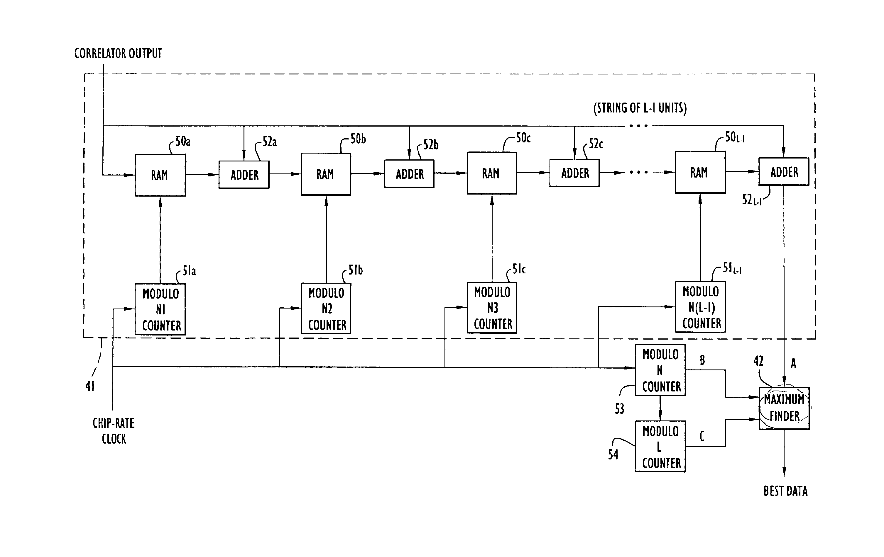
[0035]FIG. 8 is a block diagram of the maximum finder shown in FIGS. 4 and 5.

[0036]FIG. 9 is a conceptual diagram for sho...


PUM


Abstract

An apparatus and method of detecting a transmission code from a received signal, where the transmission code is composed of a plurality of dithered codes. The codes can be dithered either by varying the length of the code or varying the phase of the code according to a dither pattern and can be a stationary dither pattern that is fixed and generally known. The method includes detecting the plurality of dithered codes, and detecting the long code based on the detected dithered codes. A detection signal is generated for each detected dither code, the detection signals are combined, and the long code is detected based on the combination of detection signals. If the composite code includes M dithered codes, the correlation signals are combined by summing the M correlation sums to generate a present final sum. The long code is detected by determining a largest final sum from among the present final sum and previously generated final sums, and associating a time of the largest final sum with the time of the transmission code.

Description

CROSS REFERENCE TO RELATED APPLICATION[0002]This application claims priority from U.S. Provisional Patent Application Ser. No. 60 / 164,946, entitled “Stationary Dither Code Detection,” No. 60 / 164,952, entitled “Optimal Stationary Dither Code,” and No. 60 / 164,951 entitled “Non-stationary Dither Code Detection,” all filed Nov. 12, 1999. The disclosure of these provisional patent applications are incorporated herein by reference in its entirety.BACKGROUND OF THE INVENTION[0003]1. Field of the Invention[0004]The present invention relates to data communication systems and, more particularly, to data communication systems using codes with coding boundaries that vary according to a dithering pattern.[0005]2. Description of the Related Art[0006]Pseudonoise (PN) codes, also known as pseudorandom codes, have good autocorrelation properties and are ideal for measuring the time-of-arrival of a signal, and hence, for use in ranging applications. A high coding gain is achieved when a receiver corr...

Claims


Application Information

Patent Timeline
IPC IPC(8): H04K1/00H04B15/00
CPCH04K1/02H04J13/0077H04B1/707
Inventor CLARK, JAMES M.
Owner EXCELIS INC
Learn More