
Chattering eliminating apparatus including oscillation circuit using charging and discharging operations

a technology of eliminating apparatus and oscillation circuit, which is applied in the direction of pulse generator, pulse manipulation, pulse technique, etc., can solve the problems of control apparatus being subjected to noise, control apparatus being erroneously operated, and the effect of reducing the siz

Inactive Publication Date: 2005-03-29
NEC ELECTRONICS CORP
View PDF3 Cites 11 Cited by
  • Summary
  • Abstract
  • Description
  • Claims
  • Application Information

AI Technical Summary

Benefits of technology

It is an objection of the present invention to provide a chattering eliminating apparatus capable of decreasing the size and being not subjected to the duty ratio of a chattering phenomenon and noise.

Problems solved by technology

In an electric apparatus including a contact switch and a control apparatus receiving the output signal of the contact switch, when the contact switch is turned ON and OFF alternately for very short times, the control apparatus may erroneously operate due to a chattering phenomenon in the output signal of the contact switch.
In the above-described first prior art chattering eliminating apparatus, however, it is impossible to completely eliminate the chattering phenomenon when the input signal has a duty ratio of much larger than 50% or much smaller than 50%.
In the above-described second prior art chattering eliminating apparatus, however, since the one-shot multivibrator is usually constructed by a differential circuit, the one-shot multivibrator, i.e., the chattering eliminating apparatus is subjected to noise.
In the above-describe third prior art chattering eliminating apparatus, however, since there is no capacitor for absorbing noise, the chattering eliminating apparatus is subjected to noise.

Method used


Image

  • Chattering eliminating apparatus including oscillation circuit using charging and discharging operations
  • Chattering eliminating apparatus including oscillation circuit using charging and discharging operations
  • Chattering eliminating apparatus including oscillation circuit using charging and discharging operations

Examples


Embodiment Construction

Before the description of the preferred embodiment, prior art chattering eliminating apparatuses will be explained with reference to FIGS. 1, 2, 3, 4, 5, 6, 7 and 8.

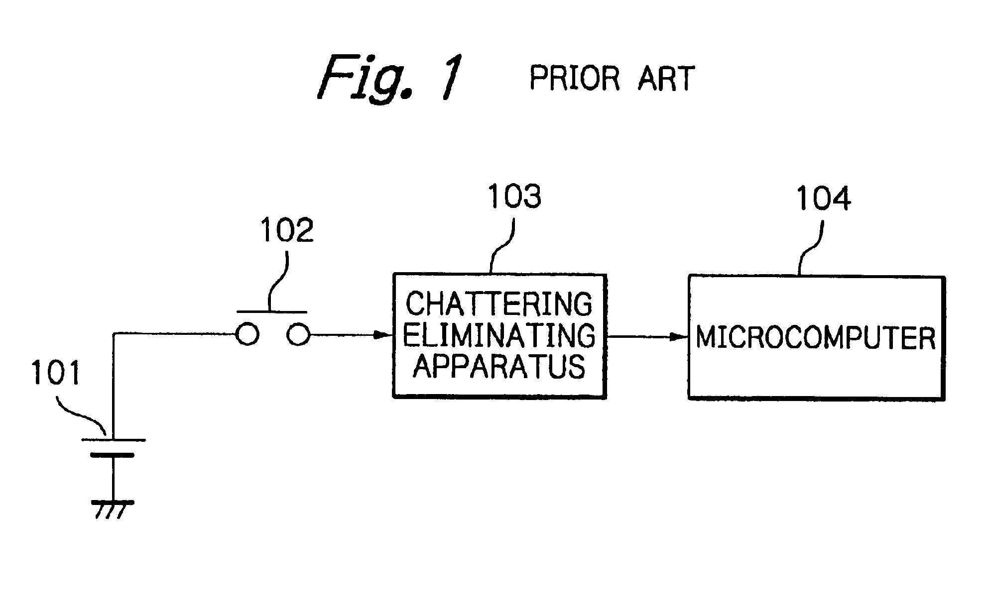
In FIG. 1, which illustrates an electric apparatus such as an automobile controlling apparatus, reference numeral 101 designates a battery connected to an ignition switch 102. The ignition switch 102 is connected via a chattering eliminating apparatus 103 to a microcomputer 104. That is, when the ignition switch 102 is turned ON and OFF alternately for very shot times, a chattering phenomenon may occur. Therefore, if the output signal of the ignition switch 102 including such a chattering phenomenon is supplied directly to the microcomputer 104, the microcomputer 104 may erroneously operate. In order to prevent the microcomputer 104 from erroneously operating, the chattering eliminating apparatus 104 is provided between the ignition switch 103 and the microcomputer 104.

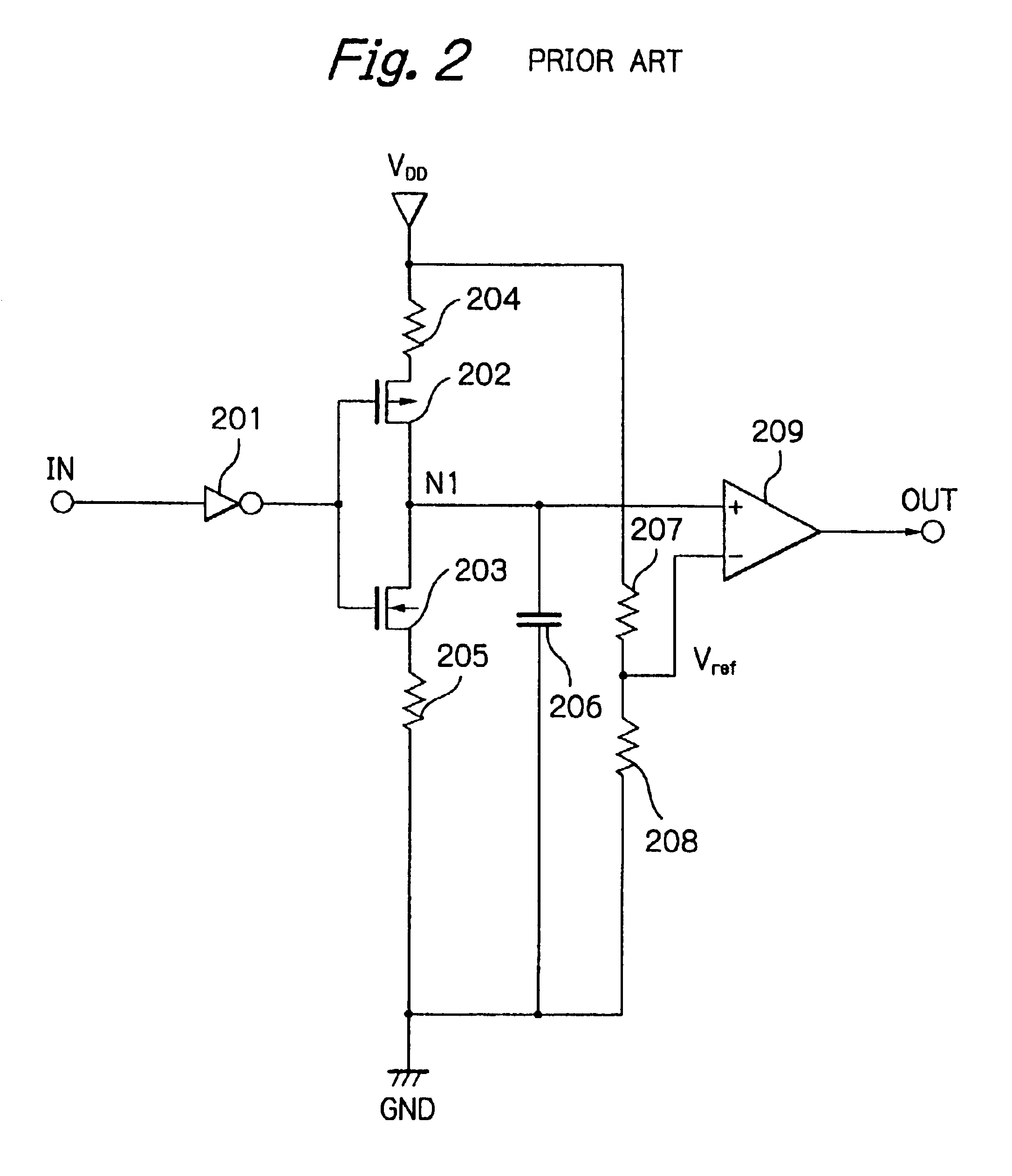
In FIG. 2, which illustrates a first chattering elim...


PUM


Abstract

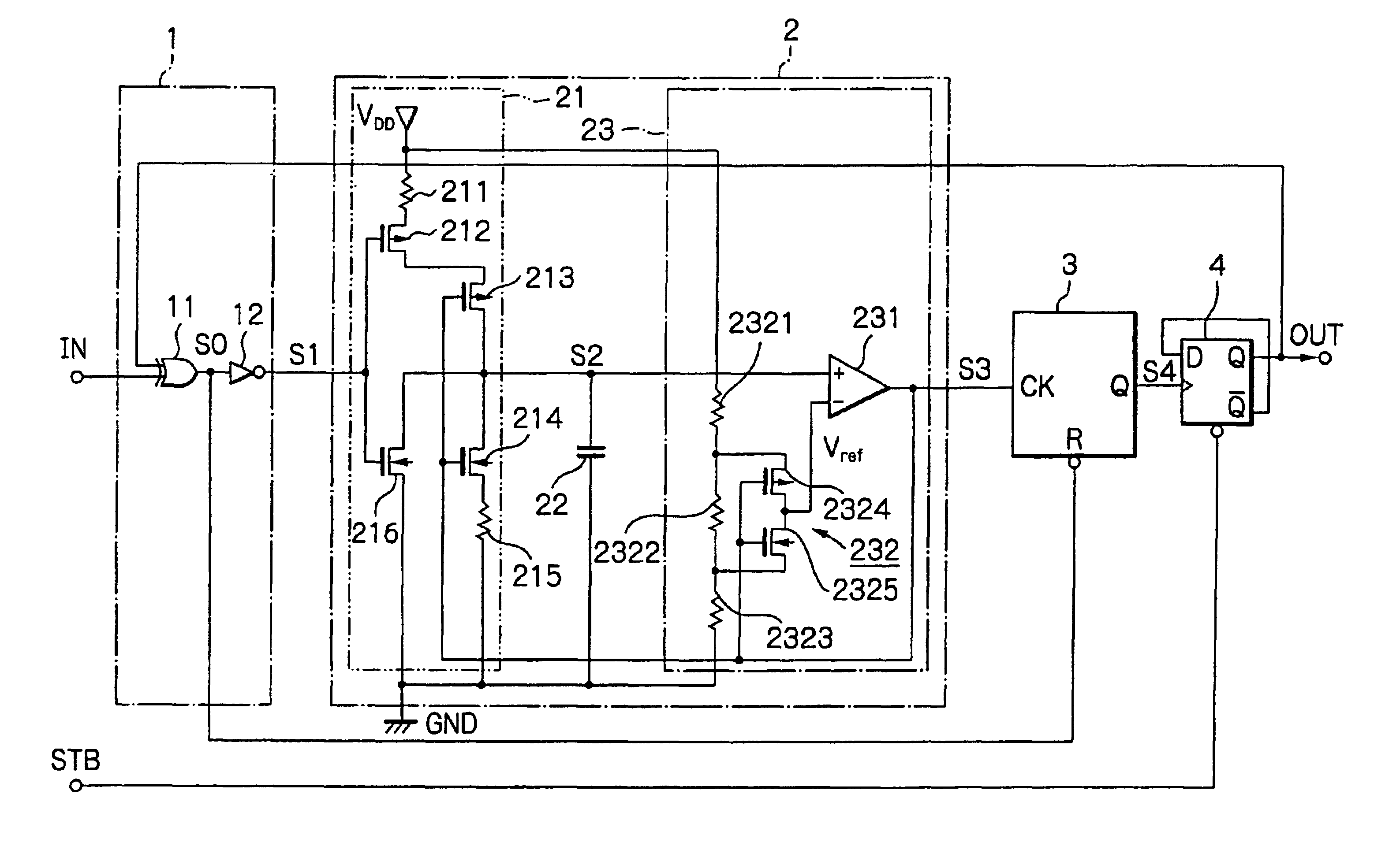
In a chattering eliminating apparatus, a coincidence circuit receives an input signal of the apparatus and an output signal of the apparatus to determine whether or not a level of the input signal of the apparatus is the same as a level of the output signal of the apparatus. An oscillation circuit carries out an oscillation operation only when the level of the input signal of the apparatus is not the same as the level of the output signal of the apparatus. A counter counts an output signal of the oscillation circuit, and is reset when the level of the input signal of the apparatus is the same as the level of the output signal of the apparatus. An output signal generating circuit inverts the level of the output signal of the apparatus when a counter value of the counter reaches a predetermined value.

Description

BACKGROUND OF THE INVENTION1. Field of the InventionThe present invention relates to a chattering eliminating apparatus.2. Description of the Related ArtIn an electric apparatus including a contact switch and a control apparatus receiving the output signal of the contact switch, when the contact switch is turned ON and OFF alternately for very short times, the control apparatus may erroneously operate due to a chattering phenomenon in the output signal of the contact switch.In order to prevent the control apparatus from erroneously operating due to the chattering phenomenon, a chattering eliminating apparatus is inserted between the contact switch and the control apparatus.A first prior art chattering eliminating apparatus (see: JP-A-2-162821) is constructed by a charging / discharging circuit for charging / discharging a capacitor in accordance with an input signal and a comparator for comparing the voltage of the capacitor with a reference voltage. This will be explained later in deta...

Claims


Application Information

Patent Timeline
Patent Type & Authority Patents(United States)
IPC IPC(8): H03K5/125H03K5/1254H03K5/1252H03K3/0231H03K3/00
CPCH03K5/1254H03K5/1252H03K3/0231
Inventor SEYA, SHUNICHI
Owner NEC ELECTRONICS CORP
Learn More