Rapid cook oven with dual flow fan assembly

a technology of convection cooking and cook oven, which is applied in the field of cooking appliances, can solve the problems of disrupting the thermal insulation layer formed around food items, and achieve the effects of eliminating any contaminates, efficient cooking of food items, and rapid cooking

Inactive Publication Date: 2005-03-29
MAYTAG
View PDF17 Cites 20 Cited by
  • Summary
  • Abstract
  • Description
  • Claims
  • Application Information

AI Technical Summary

Benefits of technology

The present invention is directed to a rapid cook oven which can more efficiently cook a food item by breaking down a thermal insulation layer maintained about the food, as well as by removing contaminates from within a convection air flow. In accordance with one embodiment of the invention, the rapid cook oven includes a microwave cooking system and a convection cooking system. The convection cooking is system is provided with a dual flow fan assembly arranged to draw in both an oven air flow from a cooking chamber and a fresh air flow from the surrounding environment. The two air flows are combined in a mixing chamber and passed over a heating element arranged within a combustion chamber prior to their introduction into the cooking chamber. By extending the time the air flow remains in the mixing chamber, the heating element provides a continuous pyrolytic combustion environment for the air flow. In this manner, contaminates carried by the air flow are subjected to a longer combustion process which substantially eliminates any contaminates.
As discussed above, the rapid cook oven of the present invention further improves cooking efficiency by removing a substantial portion of contaminates carried by the air flow. By passing the air flow over a heating element, contaminates or food byproducts carried by the air flow can be combusted prior to introduction into the cooking chamber. In this manner, smoke and other byproducts are reduced, thereby increasing the overall efficiency of the appliance.
In accordance with another embodiment, a portion of the cooking process is performed by a microwave cooking system. More specifically, the high speed air currents are preferably combined, with a varying intensity microwave energy field to further decrease the time required to cook the food item.

Problems solved by technology

As the lower temperature air flow impinges upon the food item, the thermal insulation layer formed about the food item is disrupted.

Method used


Image

  • Rapid cook oven with dual flow fan assembly
  • Rapid cook oven with dual flow fan assembly
  • Rapid cook oven with dual flow fan assembly

Examples


Embodiment Construction

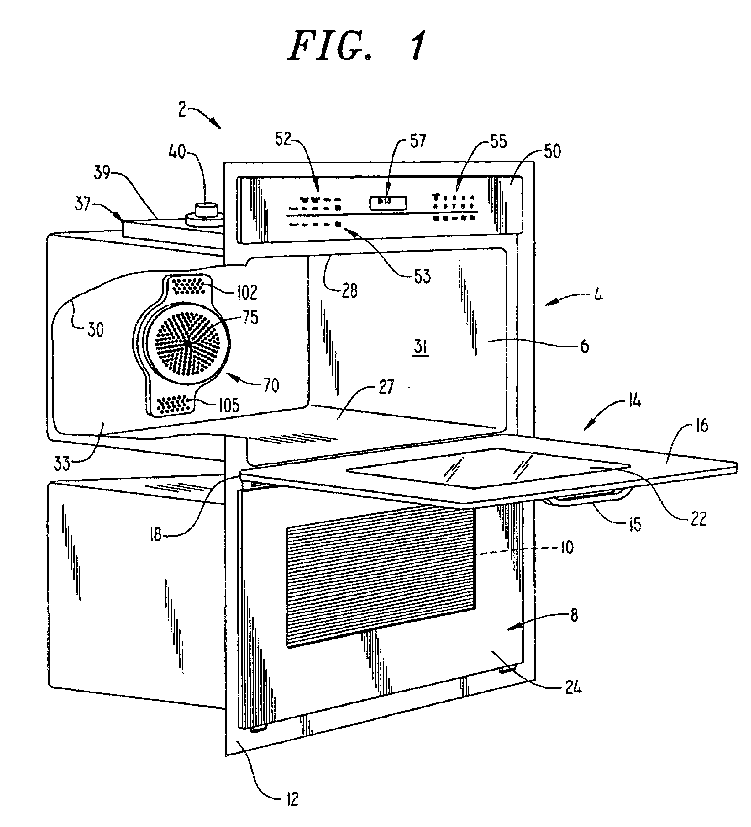
With initial reference to FIG. 1, a rapid cook oven incorporating a convection cooking system having a dual flow fan assembly constructed in accordance with the present invention is generally shown at 2. Although the actual cooking appliance 2 into which the convection cooking system assembly can be incorporated may vary, the invention is shown in connection with a dual wall oven. In the embodiment shown, cooking appliance 2 includes an upper oven 4 including upper cooking chamber or cavity 6 and a lower oven 8 including a lower cooking chamber or cavity 10. In the embodiment shown, upper oven 4 is provided to perform a combination microwave / convection cooking process, and lower oven 8 is provided to perform a standard non-convection cooking operation. As shown cooking appliance 2 includes outer frame 12 for supporting both the upper cooking chamber 6 and lower cooking chamber 10.

In a manner known in the art, a door assembly 14 is provided to selectively provide access to upper cook...


PUM


Abstract

A rapid cook convection oven is constructed to efficiently cook a food item by breaking down a thermal insulation layer maintained about the food, while effectively removing contaminates from within a convection air flow. The rapid cook oven preferably includes both a microwave cooking system and a convection cooking system. The convection cooking system is provided with a dual flow fan adapted to simultaneously draw in an oven air flow from a cooking chamber and a fresh air flow from the surroundings. In order to reduce the presence of contaminates and, by extension, smoke, the two air flows are combined in a mixing chamber and passed over a heating element arranged within a combustion chamber prior to re-entry into the cooking chamber.

Description

BACKGROUND OF THE INVENTION1. Field of the InventionThe present invention pertains to the art of cooking appliances, and more particularly, to a rapid cooking appliance including a convection cooking system having a dual flow fan or blower assembly.2. Discussion of the Prior ArtIn always striving to improve cooking appliances, manufacturers are developing cooking appliances which are capable of performing cooking processes in less time than traditional, standard thermal cooking appliances. For instance, it is known to decrease cooking time by directing forced air streams over the food item during the cooking process. The prior art actually contains several examples of producing forced air streams within an oven cavity.One method taught by the prior art is to recirculate hot air contained within an oven cavity. This technique utilizes a fan and duct system which draws in hot oven air and subsequently redirects a forced, hot air flow back into the cooking chamber. Another method taugh...

Claims


Application Information

Patent Timeline
IPC IPC(8): F24C15/32H05B6/80
CPCH05B6/6476F24C15/325
Inventor ARNTZ, TIMOTHY J.BURNS, DENNIS MICHAEL BRANDONPROFFITT, SONDRA DENICESIMS, HERBERT DUSTINSNEED, WILLIAM DARRYLWHIPPLE, JR., ROBERT Z.
Owner MAYTAG
Why Eureka
Try Eureka