
Apparatus and method for locking firearm in an open position by blocking action

a technology of blocking action and firearm, applied in the field of firearms, can solve the problems of affecting the safety of firearms, and affecting the safety of firearms, and achieving the effects of reducing the risk of firearm damage, and reducing the safety of firearms

Inactive Publication Date: 2005-03-29
O F MOSSBERG & SONS
View PDF18 Cites 10 Cited by
  • Summary
  • Abstract
  • Description
  • Claims
  • Application Information

AI Technical Summary

Benefits of technology

More specifically, one example of a suitable integral locking device comprises: a low profile, cylindrical lock body having a cylindrical through-bore; a cylindrical plunger positioned in the through-bore; and a lock key. The key and the plunger have complementary features that allow the key to engage and turn the plunger. Also, the plunger has a close-ended, helical guide groove on its outer surface, and a stationary pin is connected to and through the lock body, with its end lying within the helical guide groove. To actuate the lock, the key is used to turn the plunger. As the plunger rotates, the helical guide groove tracks along the pin, causing the plunger to extend or retract.

Problems solved by technology

Because firearms are potentially dangerous when in the wrong hands, many devices have been proposed over the years for preventing firearms from being used by unauthorized persons.
Some of these devices, e.g., trigger guard locks, while functional, are fairly cumbersome to use in that they require a user to manipulate various locking parts to secure the firearm.
Additionally, when not in use with the firearm, such locking devices must be separately stored, during which time the various loose parts can be easily lost.
These systems are convenient, but are invariably fairly expensive.
Additionally, even when the safety systems in such firearms are activated, it is typically the case that ammunition can still be chambered, which raises the possibility of accidental discharge, plus it may be difficult to determine whether or not the firearm's chamber is empty.
Additionally, there is a possibility of unauthorized use if the firearm is disassembled and the safety system thwarted.

Method used


Image

  • Apparatus and method for locking firearm in an open position by blocking action
  • Apparatus and method for locking firearm in an open position by blocking action
  • Apparatus and method for locking firearm in an open position by blocking action

Examples


Embodiment Construction

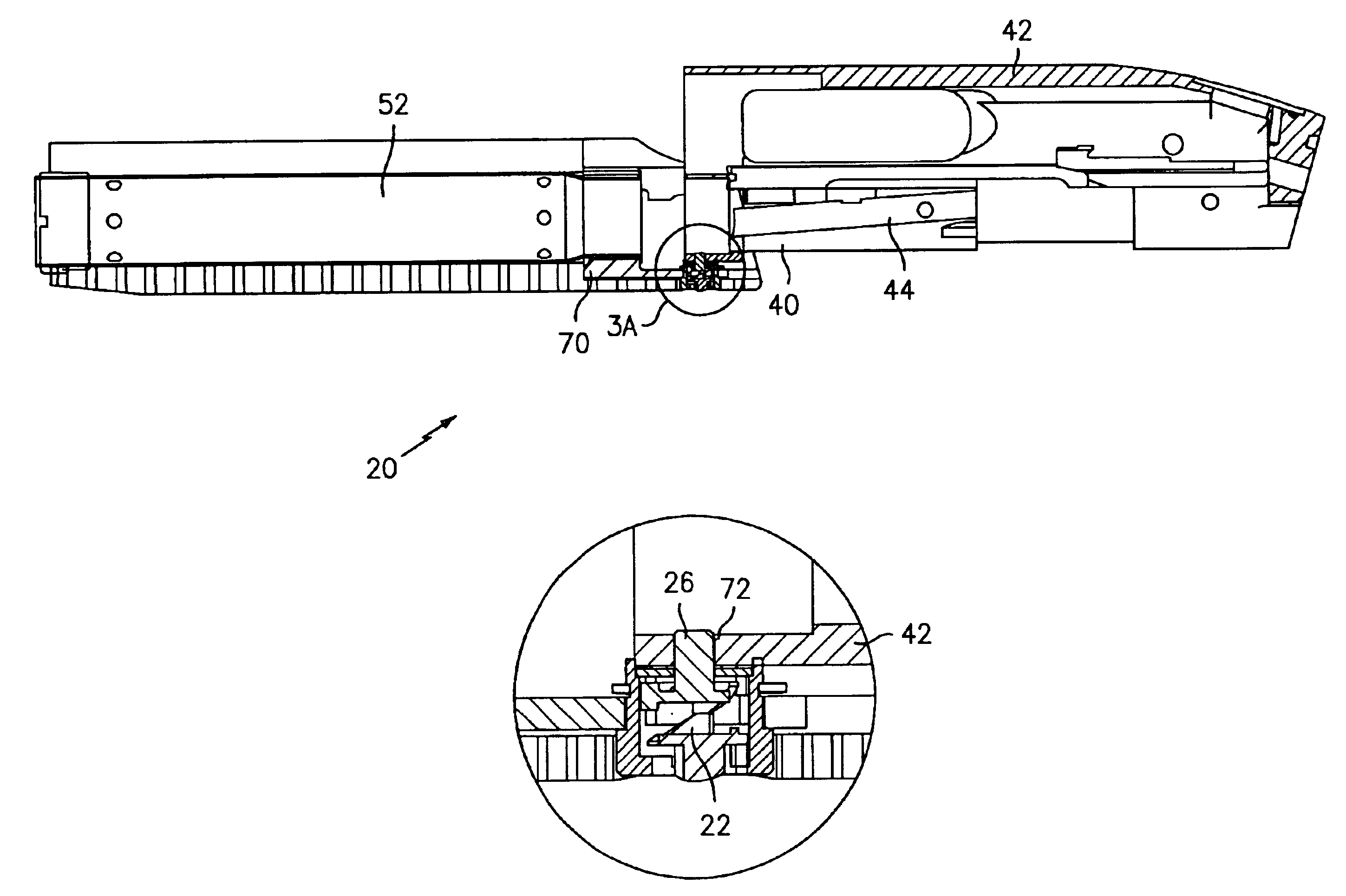
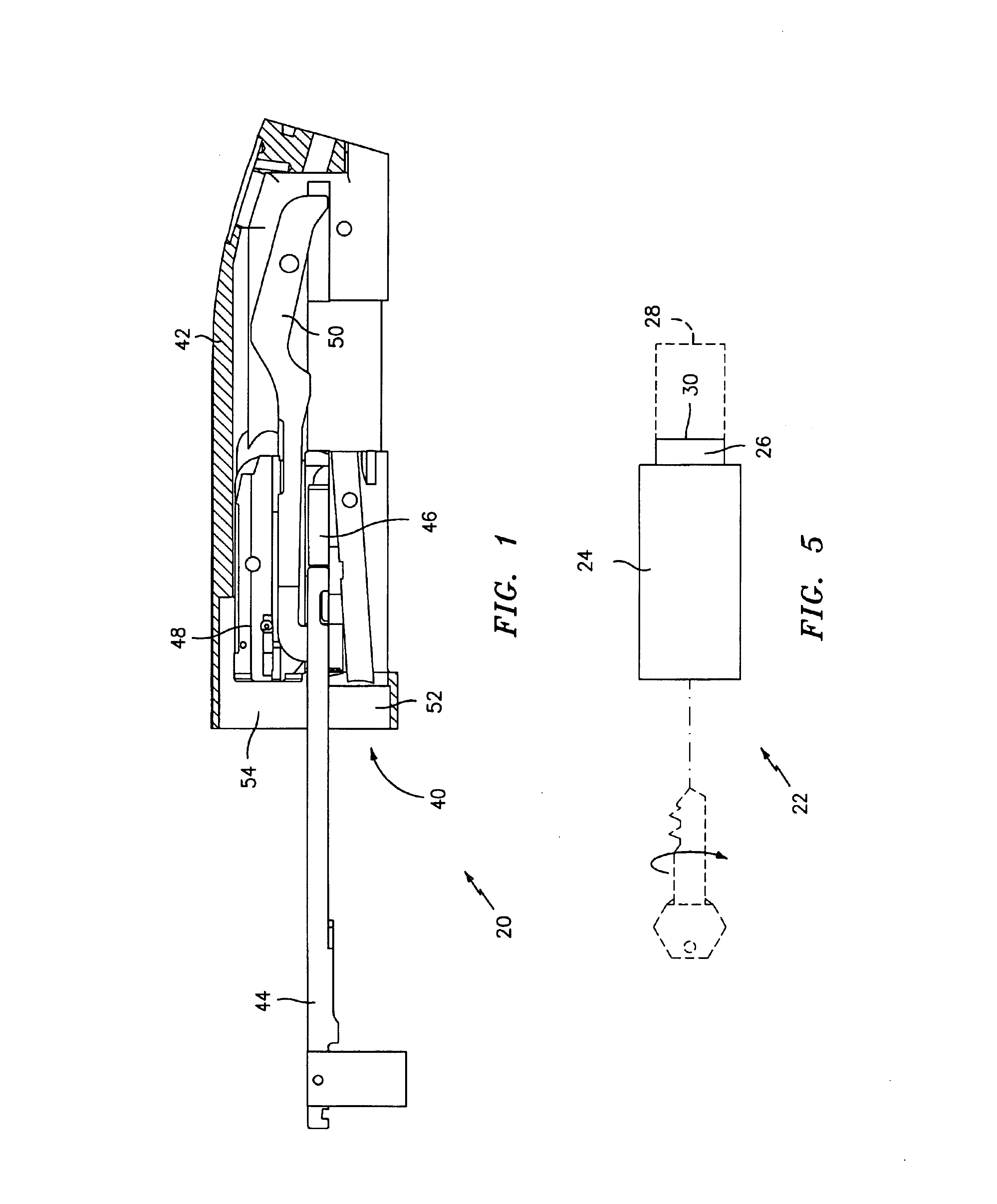
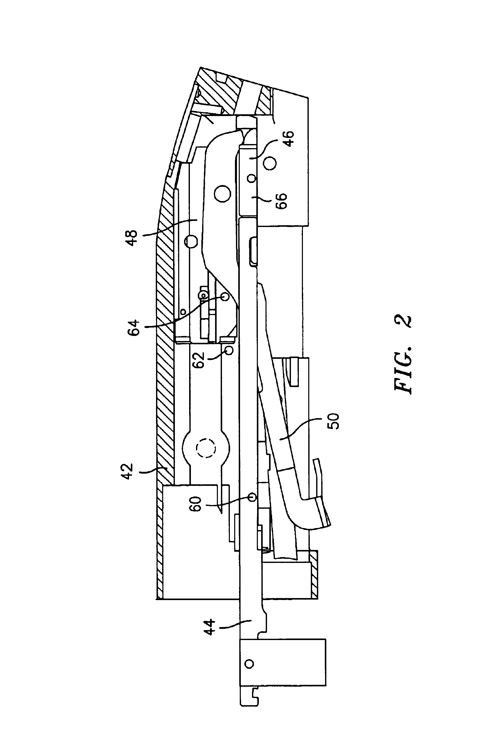
Turning now to FIGS. 1-5, a preferred embodiment of a method for locking a firearm 20, according to the present invention, will now be given. The method involves positioning an integral blocking or locking device or means 22 (hereinafter referred to as a locking device) at one of a plurality of pre-selected locations on the firearm 20, wherein the pre-selected location is preferably chosen such that: (i) when locked, the locking device 22 interferes with the firearm's action, preventing it from being closed, and the firearm from being fired; (ii) the locking device 22 can only be locked when the firearm's action is in an “open” position (i.e., an intermediate operational position wherein the firearm is physically incapable of being fired regardless of the condition of any safety mechanism or if the trigger is pulled, and wherein the chamber is visually exposed); and (iii) to the extent one is able to operatively disassemble the firearm (i.e., take the firearm apart without such dama...


PUM


Abstract

A method for locking a firearm in an “open” position involves blocking some portion of the firearm's action (internal operational mechanism) with a selectively-extendable locking device accessible from outside the firearm. More specifically, the locking device is positioned at one of a plurality of pre-selected locations on the firearm, and includes a plunger that lies retracted when the device is unlocked, and that extends into the interior of the firearm when locked. The pre-selected location is chosen such that: (i) when locked, the locking device interferes with the firearm's action, preventing it from being closed, and the firearm from being fired; (ii) the locking device can only be locked when the firearm's action is in an open position, with the chamber visually exposed; and (iii) to the extent one is able to operatively disassemble the firearm when the locking device is locked, the locking device cannot be defeated internally.

Description

FIELD OF THE INVENTIONThe present invention relates to firearms, and, more particularly, to methods and devices for securing or locking firearms.BACKGROUND OF THE INVENTIONBecause firearms are potentially dangerous when in the wrong hands, many devices have been proposed over the years for preventing firearms from being used by unauthorized persons. Some of these devices, e.g., trigger guard locks, while functional, are fairly cumbersome to use in that they require a user to manipulate various locking parts to secure the firearm. Additionally, when not in use with the firearm, such locking devices must be separately stored, during which time the various loose parts can be easily lost.Some locking or security devices are integrated into the firearms. These devices typically comprise some sort of electronics system, wherein a user has to key in a code or perform some other action to unlock the firearm for use. These systems are convenient, but are invariably fairly expensive. Addition...

Claims


Application Information

Patent Timeline
Patent Type & Authority Patents(United States)
IPC IPC(8): F41A17/00F41A17/02
CPCF41A17/02
Inventor BARTOZZI, JOSEPH H.TALBOOT, ROBERT A.HOPKINS, WAYNE E.
Owner O F MOSSBERG & SONS
Learn More