AC generator for vehicle

a technology for alternators and vehicles, applied in current collectors, dynamo-electric machines, supports/encloses/casings, etc., can solve the problems of lowering the work efficiency of brush replacement and poor workability, so as to simplify the improve the operation of brush replacement, and simplify the effect of removal and replacement of the cap

Inactive Publication Date: 2005-03-15
MITSUBISHI ELECTRIC CORP
View PDF5 Cites 1 Cited by
  • Summary
  • Abstract
  • Description
  • Claims
  • Application Information

AI Technical Summary

Benefits of technology

The present invention aims to solve the above problem and an object of the present invention is to provide an automotive alternator enabling a brush replacement operation to be improved by making a cap covering an opening portion for brush replacement formed in a case insertable to simplify removal and replacement of the cap.
In an automotive alternator according to the present invention, first and second ends of a shaft are rotatably supported in a case, and a rotor is fixed to the shaft and is rotatably disposed inside the case. A slip ring is fixed to the shaft, and a stator is fixed to the case so as to surround the rotor. A brush holder through which a brush insertion aperture is disposed and into a head portion of which a cover is fitted is disposed inside the case such that an aperture direction of the brush insertion aperture is perpendicular to an axial direction of the shaft, and a brush is disposed so as to be held inside the brush insertion aperture and slide in contact with the slip ring. An opening portion is formed in a portion of the case facing the cover, and a cap is insertably mounted to this opening portion. Thus, an automotive alternator is provided in which removal and replacement of the cap is simplified, enabling the brush to be changed without dismantling the case.

Problems solved by technology

Generally, a brush holding apparatus in an automotive alternator is mounted internally in a tightly-closed case, making it necessary to dismantle the case during brush replacement, thereby making workability extremely poor.
However, in this conventional automotive alternator, because the cover 99 is mounted to the rear bracket 84a by means of fastening by the screws 100, one problem has been that removal and replacement of the screws 100 is required in a narrow engine compartment, lowering brush replacement work efficiency.

Method used


Image

  • AC generator for vehicle
  • AC generator for vehicle
  • AC generator for vehicle

Examples


embodiment 1

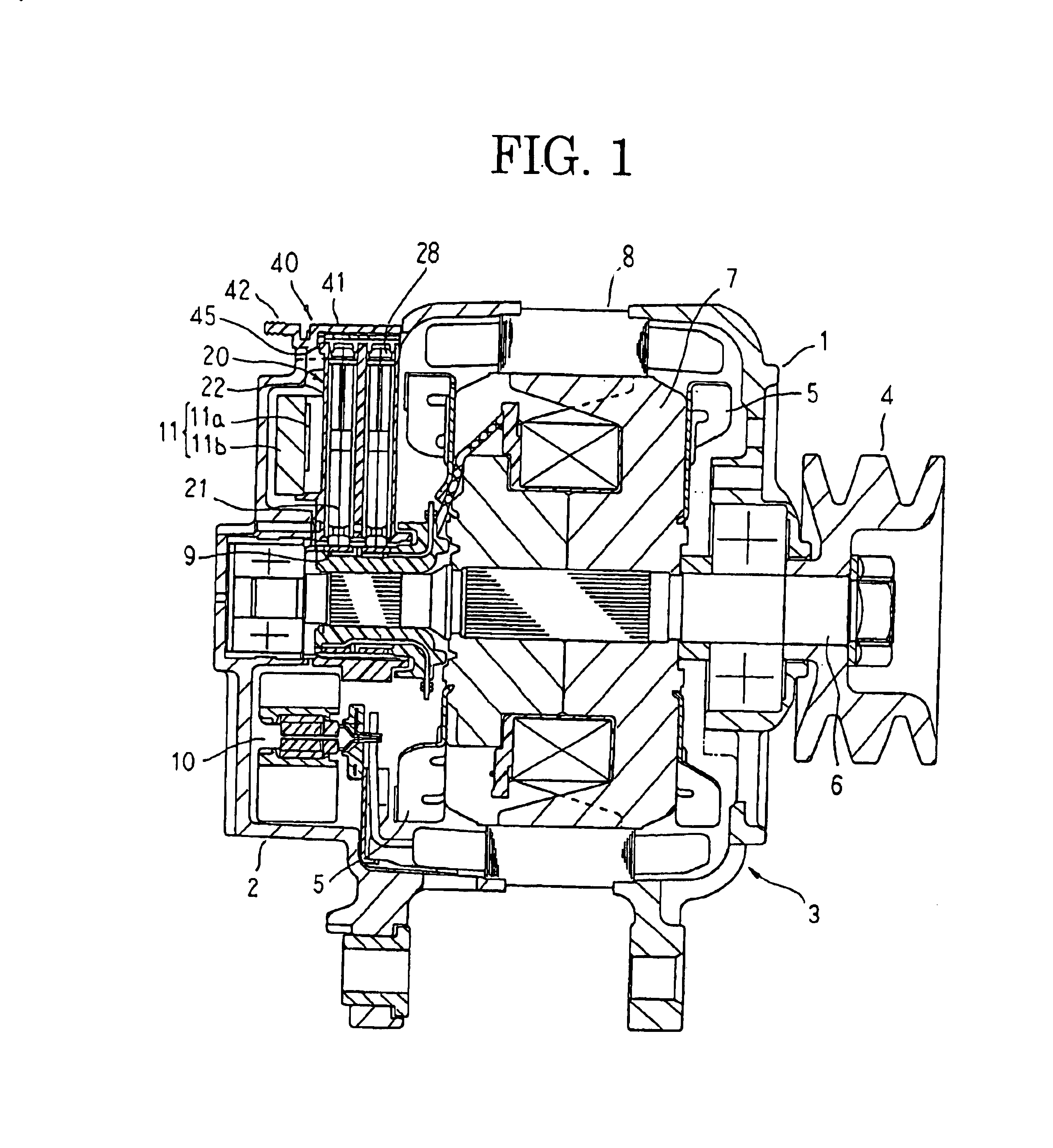
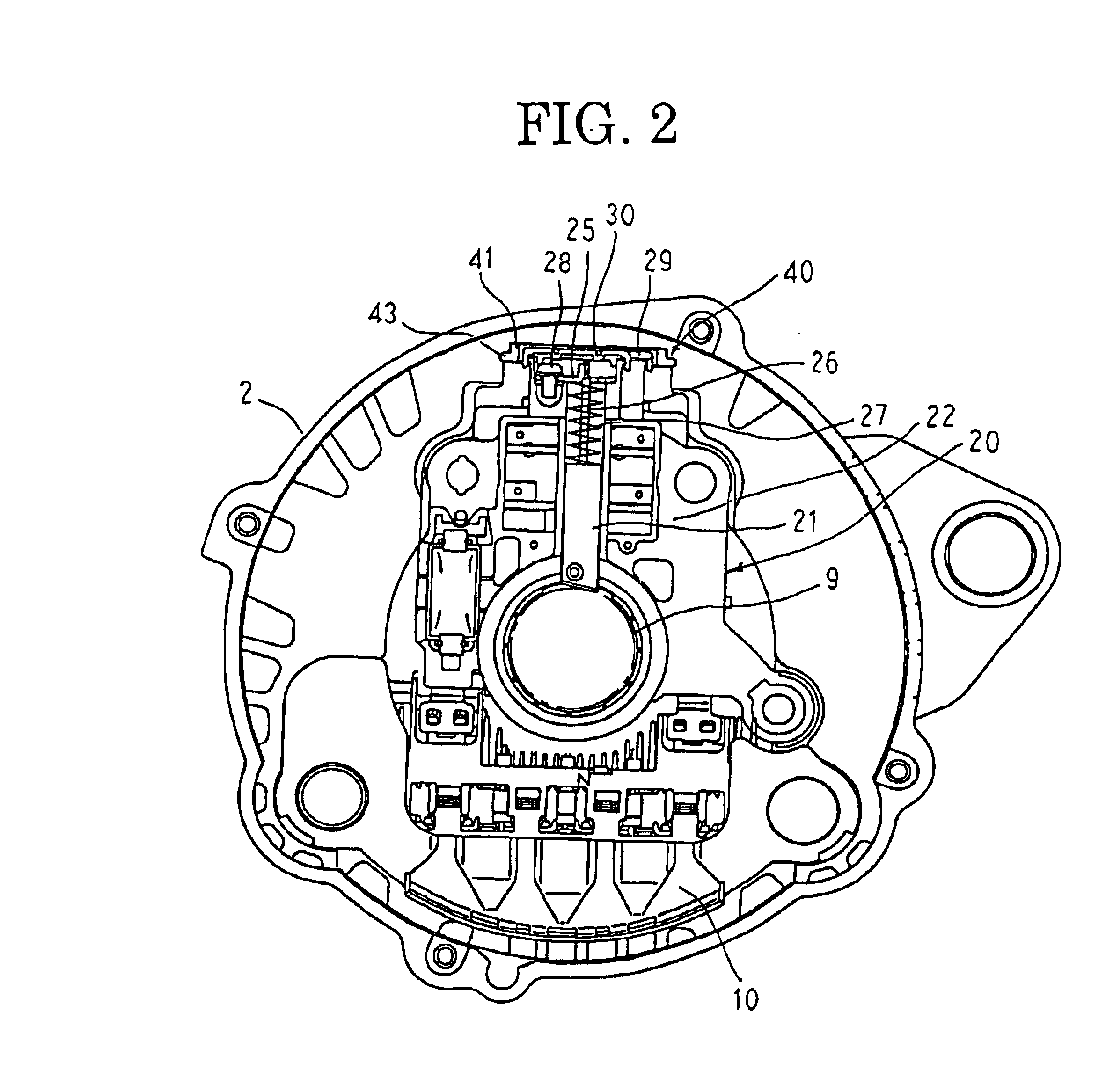
FIG. 1 is a longitudinal section showing an automotive alternator according to Embodiment 1 of the present invention, FIG. 2 is a plan partly in section showing a rear bracket end of an interior portion of the automotive alternator according to Embodiment 1 of the present invention, FIG. 3 is a plan showing a brush holding apparatus used in the automotive alternator according to Embodiment 1 of the present invention with a cover removed, FIG. 4 is a plan showing the brush holding apparatus used in the automotive alternator according to Embodiment 1 of the present invention, FIG. 5 is a front elevation showing the brush holding apparatus used in the automotive alternator according to Embodiment 1 of the present invention, FIG. 6 is a front elevation showing a brush assembly of the brush holding apparatus used in the automotive alternator according to Embodiment 1 of the present invention, FIG. 7 is a side elevation showing the brush assembly of the brush holding apparatus used in the...

embodiment 2

FIG. 13 is a plan showing a cap used in an automotive alternator according to Embodiment 2 of the present invention, FIG. 14 is a side elevation of the cap shown in FIG. 13 viewed from direction A, FIG. 15 is a side elevation of the cap shown in FIG. 13 viewed from direction B, FIG. 16 is a perspective showing a rear bracket of the automotive alternator according to Embodiment 2 of the present invention with the cap mounted, FIG. 17 is a cross section taken along line XVII—XVII in FIG. 16 viewed from the direction of the arrows, and FIG. 18 is a perspective showing the rear bracket of the automotive alternator according to Embodiment 2 of the present invention with the cap removed.

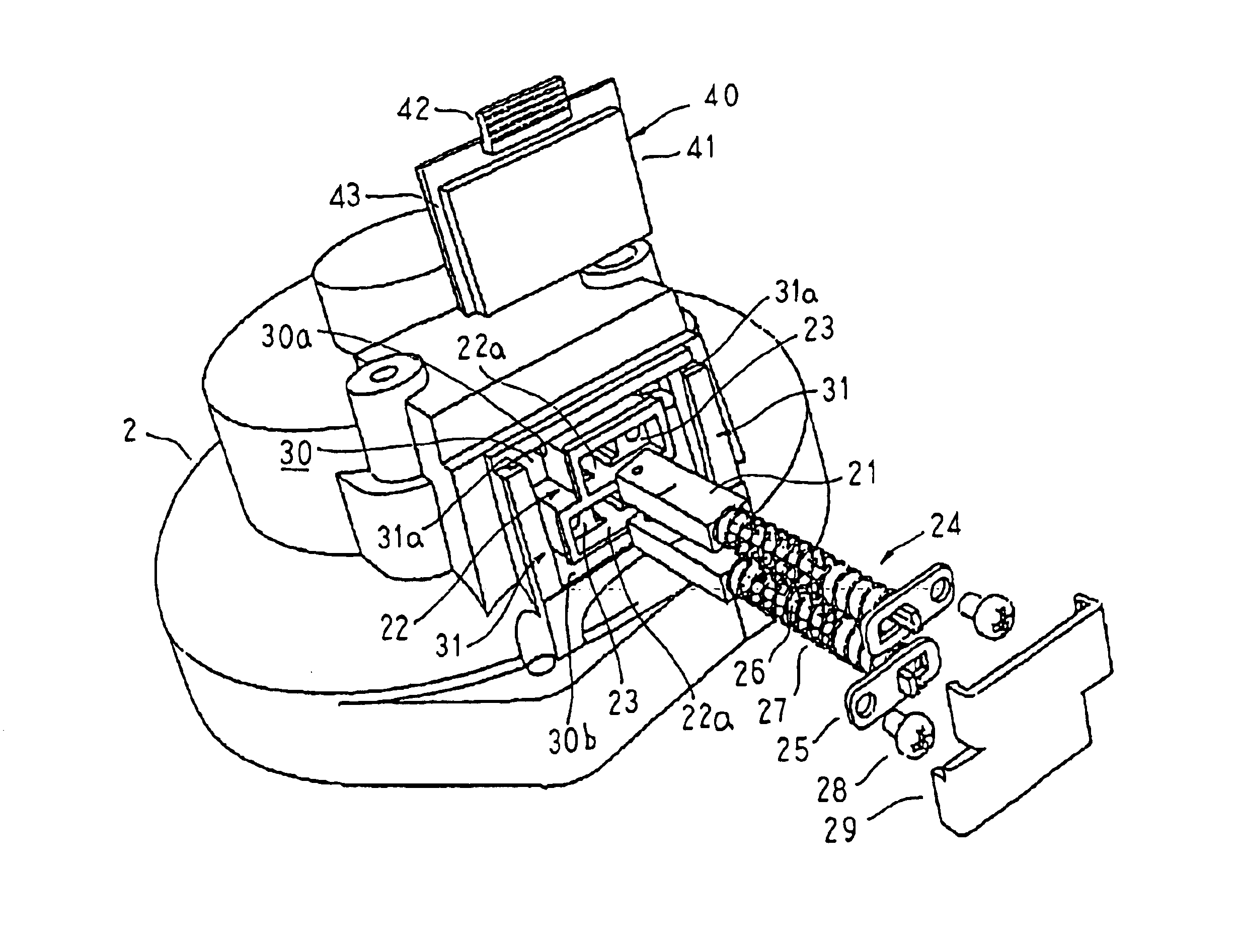
In Embodiment 2, at rear-end ends of side portions of a rectangular opening portion 30A in the rear bracket 2, a pair of side walls 31A are formed facing each other parallel to the axial direction of the shaft 6. Grooves 31a parallel to the axial direction are formed in the facing inner wall surfaces of th...

embodiment 3

FIG. 19 is a plan showing a cap used in an automotive alternator according to Embodiment 3 of the present invention, FIG. 20 is a side elevation of the cap shown in FIG. 19 viewed from direction A, FIG. 21 is a side elevation of the cap shown in FIG. 19 viewed from direction B, FIG. 22 is a perspective showing a rear bracket of the automotive alternator according to Embodiment 3 of the present invention with the cap mounted, and FIG. 23 is a perspective showing the rear bracket of the automotive alternator according to Embodiment 3 of the present invention with the cap removed.

In Embodiment 3, at rear-end ends of side portions of a rectangular opening portion 30B in the rear bracket 2, a pair of side walls 31B are formed facing each other parallel to the axial direction of the shaft 6. Grooves 31a parallel to the axial direction are formed in the facing inner wall surfaces of the pair of side walls 31B. Moreover, an upper surface of a bracket-shaped wall constituted by the front-end...


PUM


Abstract

The present invention provides an automotive alternator enabling a brush replacement operation to be improved by making a cap covering an opening portion for brush replacement formed in a case insertable to simplify removal and replacement of the cap.A brush holder through which a brush insertion aperture is disposed and into a head portion of which a cover is fitted is disposed inside a case such that an aperture direction of the brush insertion aperture is perpendicular to an axial direction of a shaft, and a brush is disposed so as to be held inside the brush insertion aperture and slide in contact with a slip ring fixed to the shaft. An opening portion for brush replacement is formed in a portion of the case facing the cover, and a cap is insertably mounted to this opening portion.

Description

TECHNICAL FIELDThe present invention relates to an automotive alternator driven by an internal combustion engine, for example, and particularly relates to a case construction for improving brush replacement in a brush holding apparatus.BACKGROUND ARTGenerally, a brush holding apparatus in an automotive alternator is mounted internally in a tightly-closed case, making it necessary to dismantle the case during brush replacement, thereby making workability extremely poor.Thus, automotive alternators in which an opening is disposed in a portion of the case facing the brush holding apparatus, enabling the brushes to be changed through the opening, have been proposed in Japanese Utility Model Laid-Open No. SHO 51-87205, Japanese Patent Laid-Open No. SHO 51-66409, etc., for example.FIGS. 29 and 30 are a longitudinal section and a plan, respectively, showing a vicinity of the brush holding apparatus of the conventional automotive alternator described in Japanese Patent Laid-Open No. SHO 51-...

Claims


Application Information

Patent Timeline
Patent Type & Authority Patents(United States)
IPC IPC(8): H02K5/14
CPCH02K5/148H02K5/141H02K13/00
Inventor INOUE, HIROKAZUTAKAHASHI, TOMOKIHAYASHI, HIDEYUKI
Owner MITSUBISHI ELECTRIC CORP
Why Eureka
Try Eureka