Aortic shunt with spinal perfusion and cooling device

a cooling device and shunt technology, applied in the field of medical devices, can solve the problems of inability to insert the device, the shunt fails to specifically perfuse the spinal arteries, and the risk of thromboembolism, so as to avoid the risk of systemic hemorrhage and reduce the risk of embolism

Inactive Publication Date: 2005-03-15
ZOLL CIRCULATION
View PDF11 Cites 14 Cited by
  • Summary
  • Abstract
  • Description
  • Claims
  • Application Information

AI Technical Summary

Benefits of technology

The present invention provides intravascular devices and methods for perfusing the spinal arteries during surgeries. The devices include an intra-aortic component and an extra-aortic component, which are both attached to a shunt. The intra-aortic component is a catheter with a shunt releasably mounted on its distal end. The shunt has a tubular member with a valve for controlling blood flow and an expandable occluder for preventing blood leakage. The extra-aortic component is a second tubular member with a valve for controlling perfusion pressure. The devices can be used for hypothermic perfusion and can be inserted into various arteries, such as the aorta, iliac, mesenteric, or renal arteries. The advantages of using the devices include providing perfusion to the spinal arteries throughout the entire vascular procedure, reducing the risk of embolization, and avoiding the need for a pump and systemic heparinization.

Problems solved by technology

However, the shunt fails to specifically perfuse the spinal arteries.
Disadvantages associated with this device are that (1) puncturing of the aorta is required for inserting an occluder, (2) arterial clamping is required, which carries the risk of thromboembolism, (3) the aorta needs to be incised for inserting catheters into the spinal arteries.
However, the device cannot be inserted prior to severing of the aorta and therefore failed to eliminate the need for aortic cross clamping and puncture.
However, this system still requires aortic clamping and perforation.

Method used


Image

  • Aortic shunt with spinal perfusion and cooling device
  • Aortic shunt with spinal perfusion and cooling device
  • Aortic shunt with spinal perfusion and cooling device

Examples


Embodiment Construction

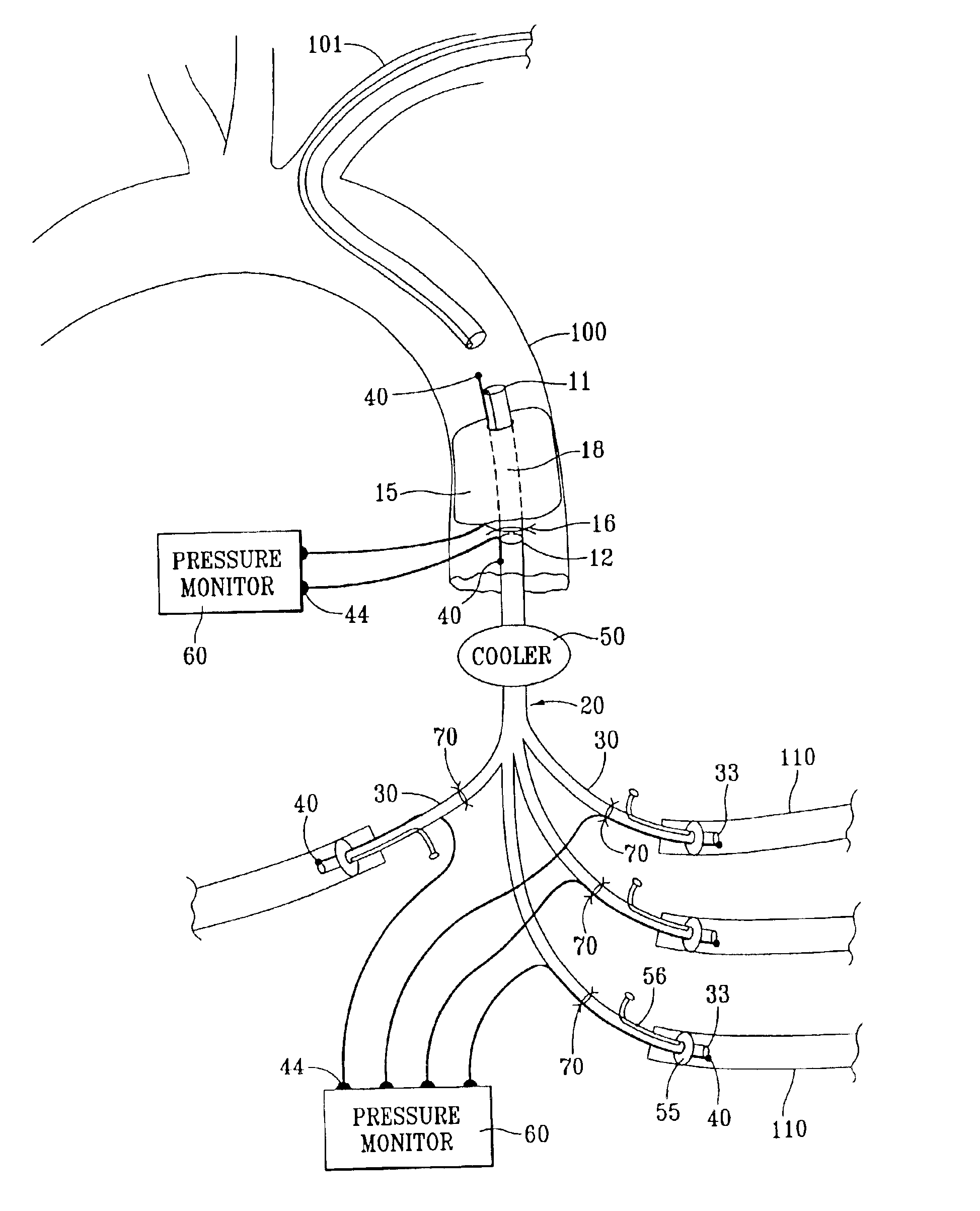
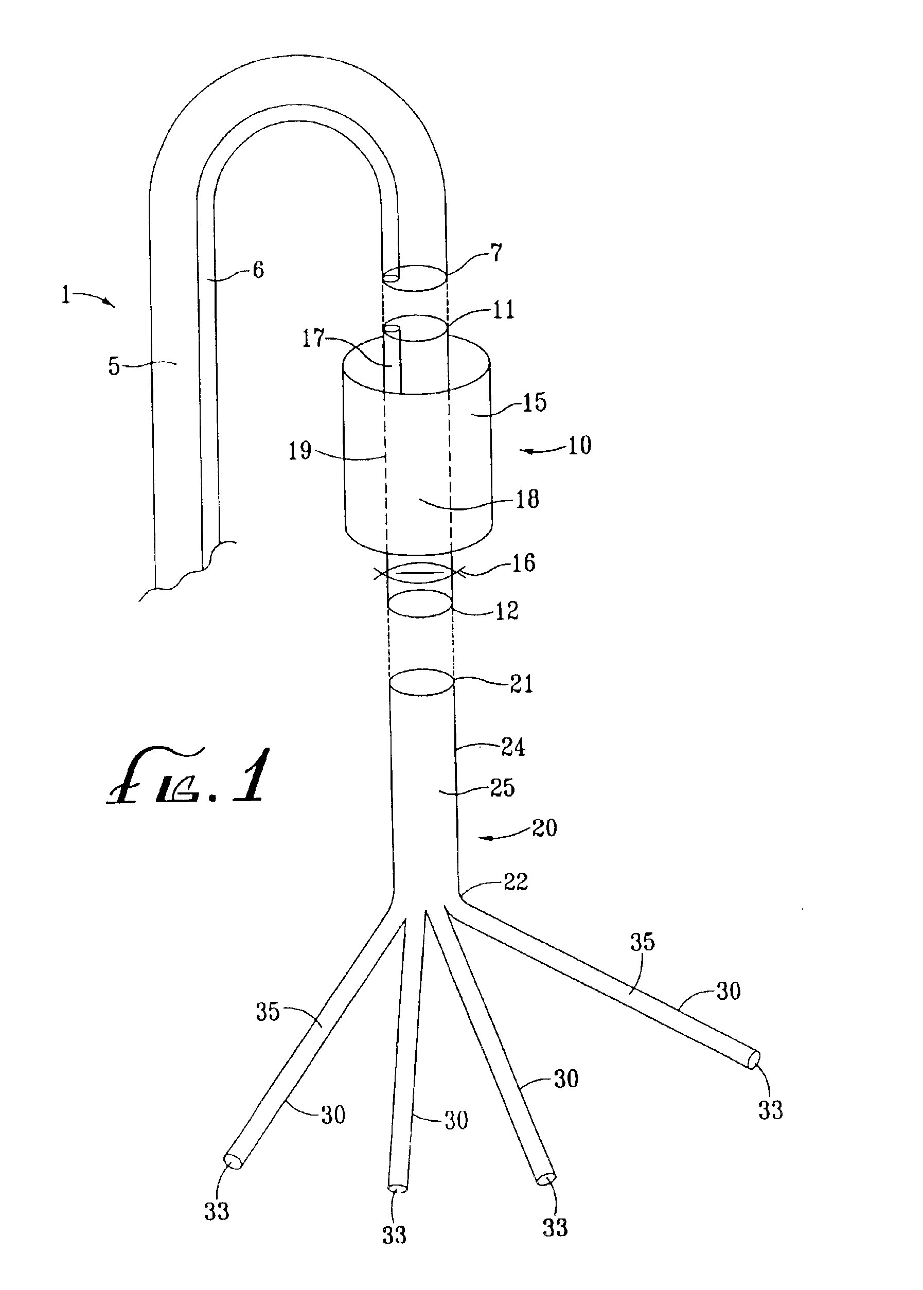
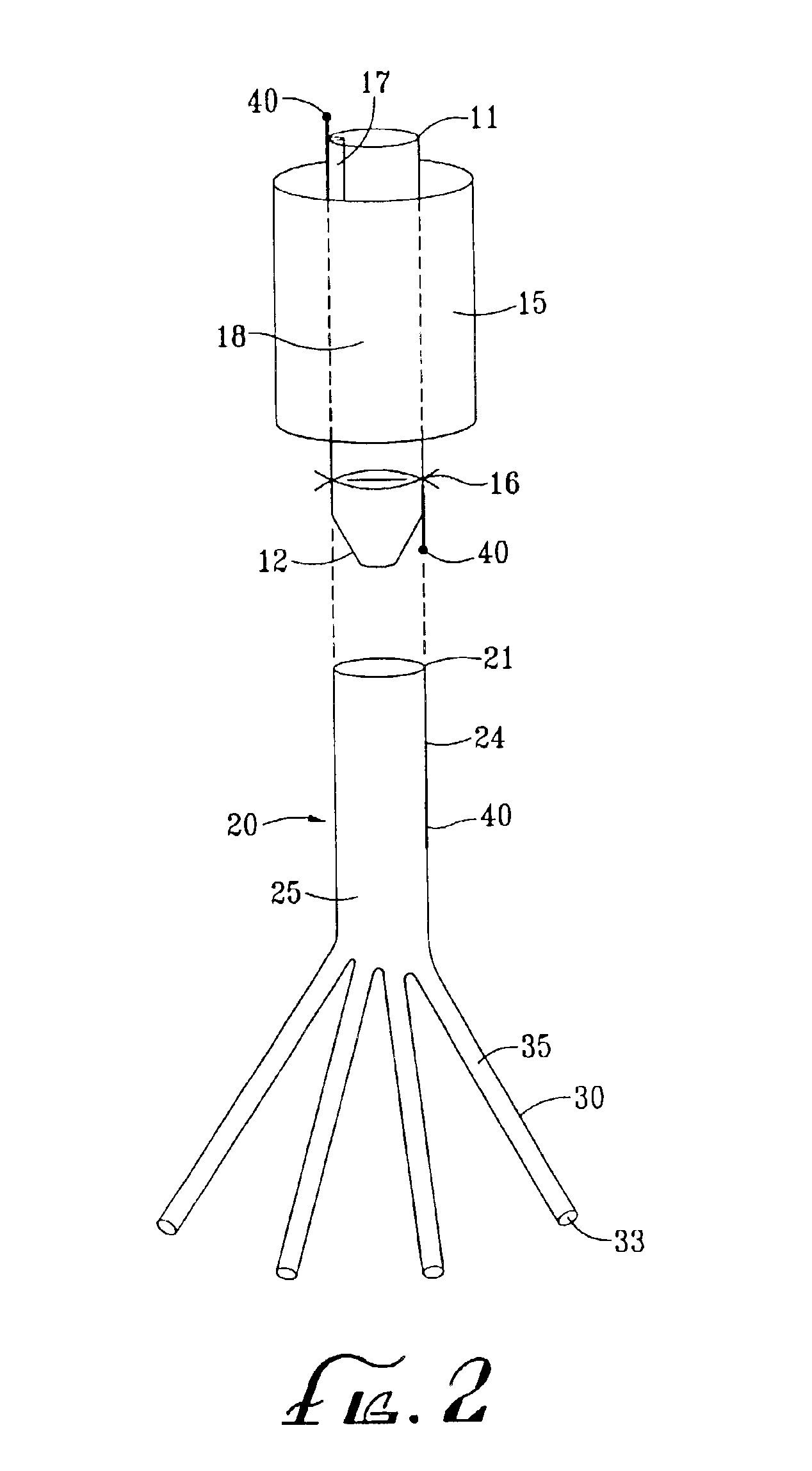
Referring now to the drawings, an embodiment of the intravascular device for perfusing a patient's spinal vasculature during thoracoabdominal surgery is depicted in FIG. 1. The device generally comprises an intra-aortic component having catheter 1 and aortic shunt 10, and an extra-aortic component 20. Catheter 1 has lumen 5 communicating with a proximal end and distal end 7. Aortic shunt 10 comprises tubular member 19 which has lumen 18 communicating with proximal end 11 and distal end 12. First end 11 of the shunt is releasably mounted to distal end 7 of the catheter. Expandable occluder 15, shown here as an inflatable cylindrical balloon, is disposed about tubular member 19, and communicates with inflation lumen 17. When shunt 10 is mounted to catheter 1, inflation lumen 17 communicates with inflation lumen 6 of the catheter. Shunt 10 also includes valve 16 distal to occluder 15 for controlling fluid or blood flow through lumen 18 of the shunt.

Second component 20 comprises second ...


PUM


Abstract

An intravascular device comprising an intra-aortic and extra-aortic component for perfusing the spinal arteries during thoracoabdominal surgeries. The intra-aortic component comprises a catheter having a shunt releasably mounted on a distal end of the catheter. An expandable occluder is disposed about the shunt for occluding the aortic lumen. The extra-aortic component comprises a tubular member having a lumen communicating with a first end and a second end. The first end is adapted for attachment to the shunt. The second end of the second tubular member is attached to a plurality of tubular branches. A cooler may be attached to the second tubular member for providing hypothermic perfusion. When the intra-aortic component is attached to the extra-aortic component, blood flows from the proximal aorta to the spinal arteries through the lumens of the tubular branches. Methods of using the device for spinal perfusion during thoracoabdominal surgeries herein are also disclosed.

Description

FIELD OF THE INVENTIONThe present invention generally relates to medical devices for perfusing a patient's spinal vasculature during thoracoabdominal surgery. More particularly, the devices comprise an aortic shunt which is releasably mounted to a catheter at a first end of the devices and to a tubular member having tubular branches adapted for insertion into spinal arteries at a second end. The shunt also includes an expandable occluder for occluding the aortic lumen and a valve for controlling fluid or blood flow to the spinal arteries. A cooler may be included for providing hypothermic perfusion to the spinal cord.BACKGROUND OF THE INVENTIONThoracoabdominal surgeries, including abdominal aortic aneurysm repair, aortic dissection repair, and aortic thrombectomy, are associated with substantial neurologic morbidity. During abdominal aortic aneurysm repair, for example, an arterial clamp is placed across the aorta for total occlusion and the abdominal aorta is incised or transected ...

Claims


Application Information

Patent Timeline
Patent Type & Authority Patents(United States)
IPC IPC(8): A61M25/10A61F7/12A61F2/958
CPCA61M25/10A61F7/12A61F2007/126A61M2210/127A61M2025/1052A61M2205/3606
Inventor BARBUT, DENISE R.
Owner ZOLL CIRCULATION
Why Eureka
Try Eureka