
Bowl scraper and related attachment system for mixing machine

a technology of bowl scraper and attachment system, which is applied in the field of bowl scraper of mixing machine and related attachment system, can solve the problems of increasing manufacturing cos

Inactive Publication Date: 2005-03-15
PREMARK FEG L L C
View PDF32 Cites 15 Cited by
  • Summary
  • Abstract
  • Description
  • Claims
  • Application Information

AI Technical Summary

Benefits of technology

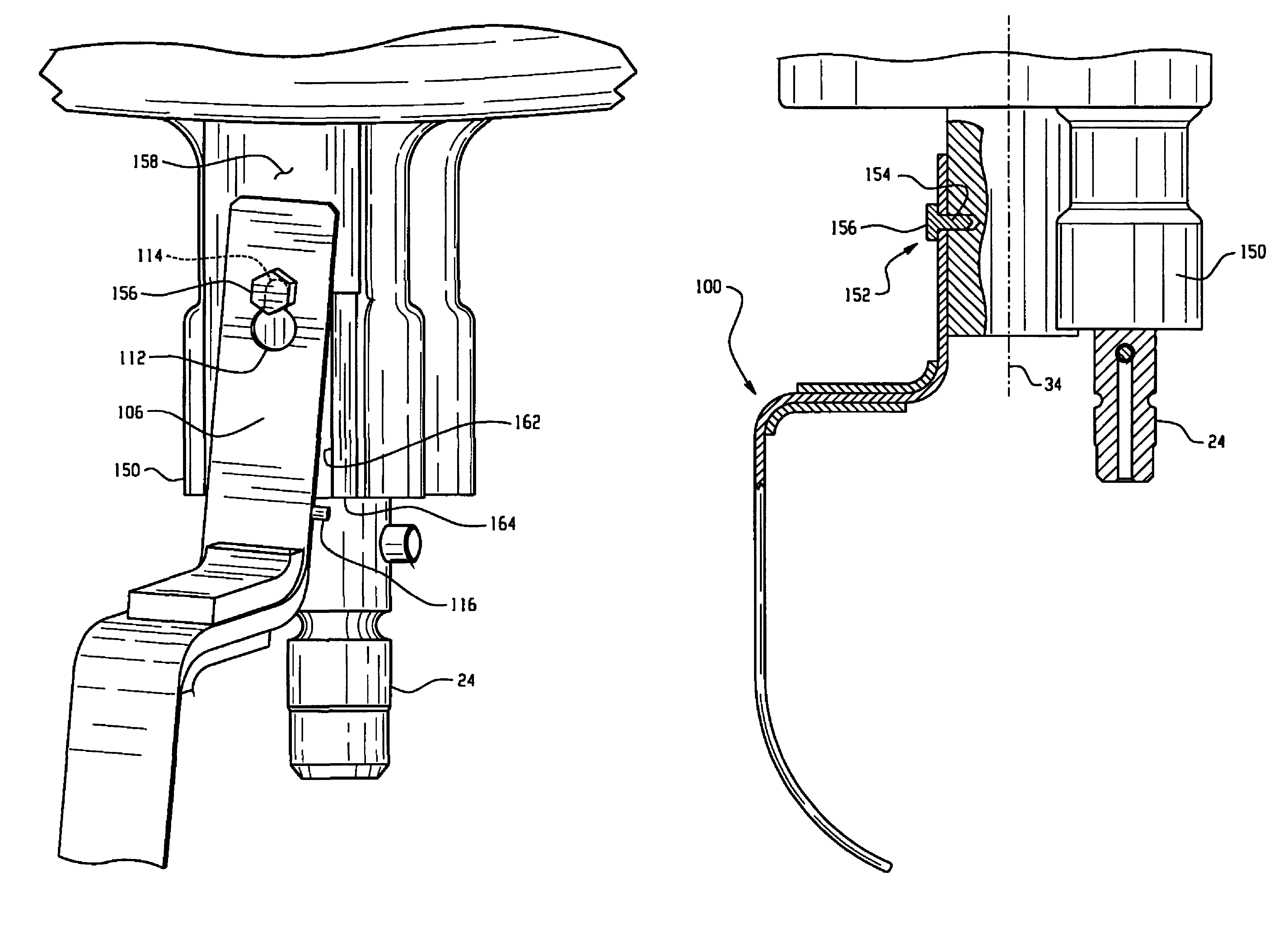
In one aspect, in a mixing machine including a rotatable support extending from a mixer head, a connecting and support system for quickly connecting and disconnecting a bowl scraper is provided. The system includes a bowl scraper attachment arm including a through opening and a protrusion extending from the arm and positioned lower than the through opening. A mount protrusion extends laterally from the rotatable support and including a shaft and an enlarged head, the enlarged head sized to prevent passage through at least a portion of the through opening. A shoulder is located on the support and a stop surface is located on the support and positioned lower than the mount protrusion. When the bowl scraper is connected to the support in an operating position, the mount protrusion extends through the portion of the through opening, part of the attachment arm is located adjacent the shoulder for preventing rotation of the bowl scraper about the mount protrusion in at least one direction, and the attachment arm protrusion is located adjacent the stop surface for preventing movement of the bowl scraper in at least one direction along the through opening.
In a further aspect, a method of maintaining a bowl scraper on a mixing machine during a scraping operation involves connecting the bowl scraper on a rotatable support via passage of an opening in an attachment arm of the bowl scraper over a mount protrusion of the support; urging a portion of the attachment arm against a side shoulder of the support by forces exerted on the bowl scraper during its scraping operation to prevent rotation of the attachment arm about the mount protrusion; and urging a portion of the bowl scraper against a stop surface of the support by upward forces exerted on the bowl scraper during its scraping operation to prevent upward movement of the bowl scraper.

Problems solved by technology

The described arrangement in U.S. Pat. No. 4,946,285 requires the use of moving parts and therefore increases manufacturing costs.

Method used


Image

  • Bowl scraper and related attachment system for mixing machine
  • Bowl scraper and related attachment system for mixing machine
  • Bowl scraper and related attachment system for mixing machine

Examples


Embodiment Construction

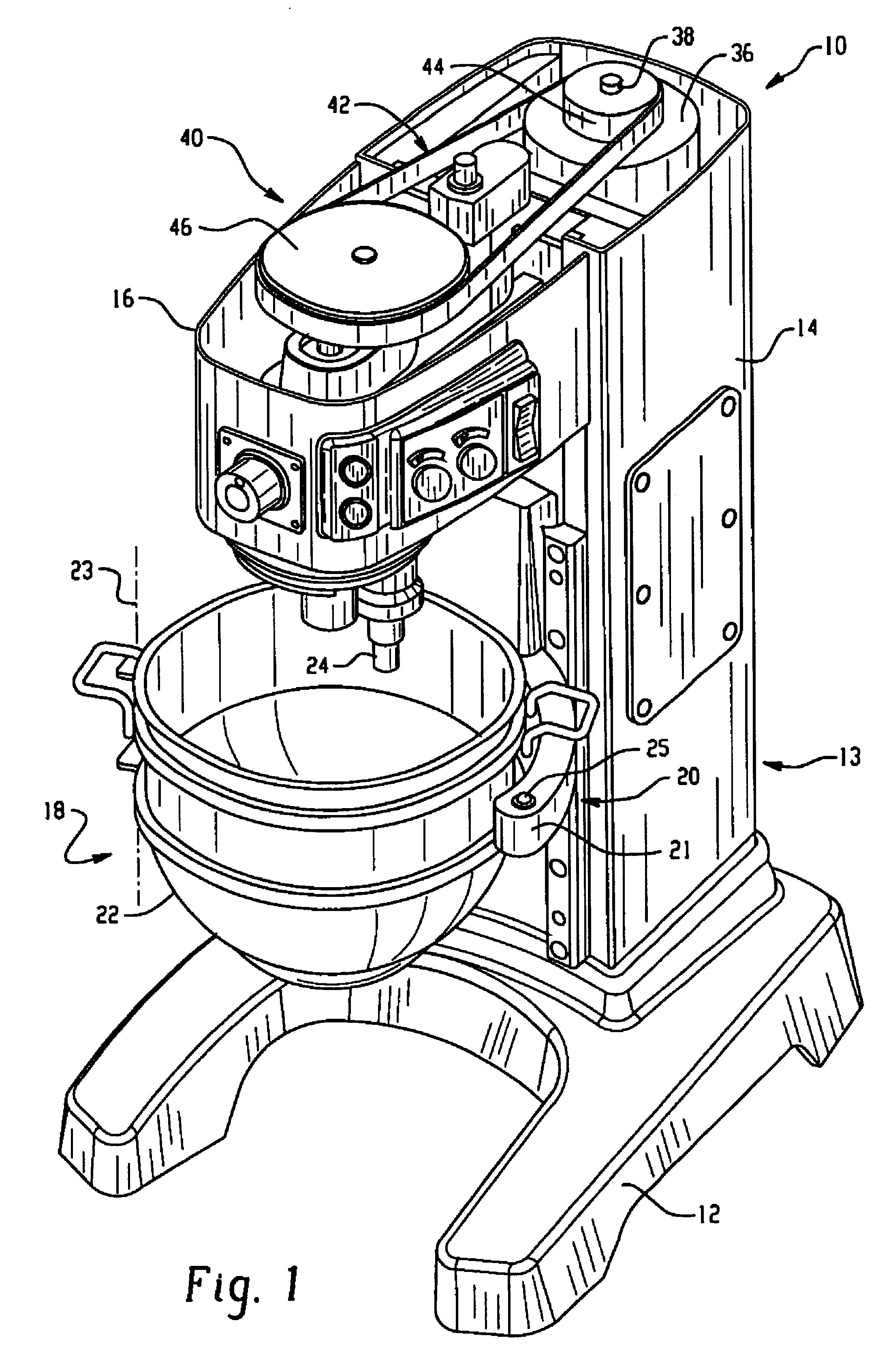
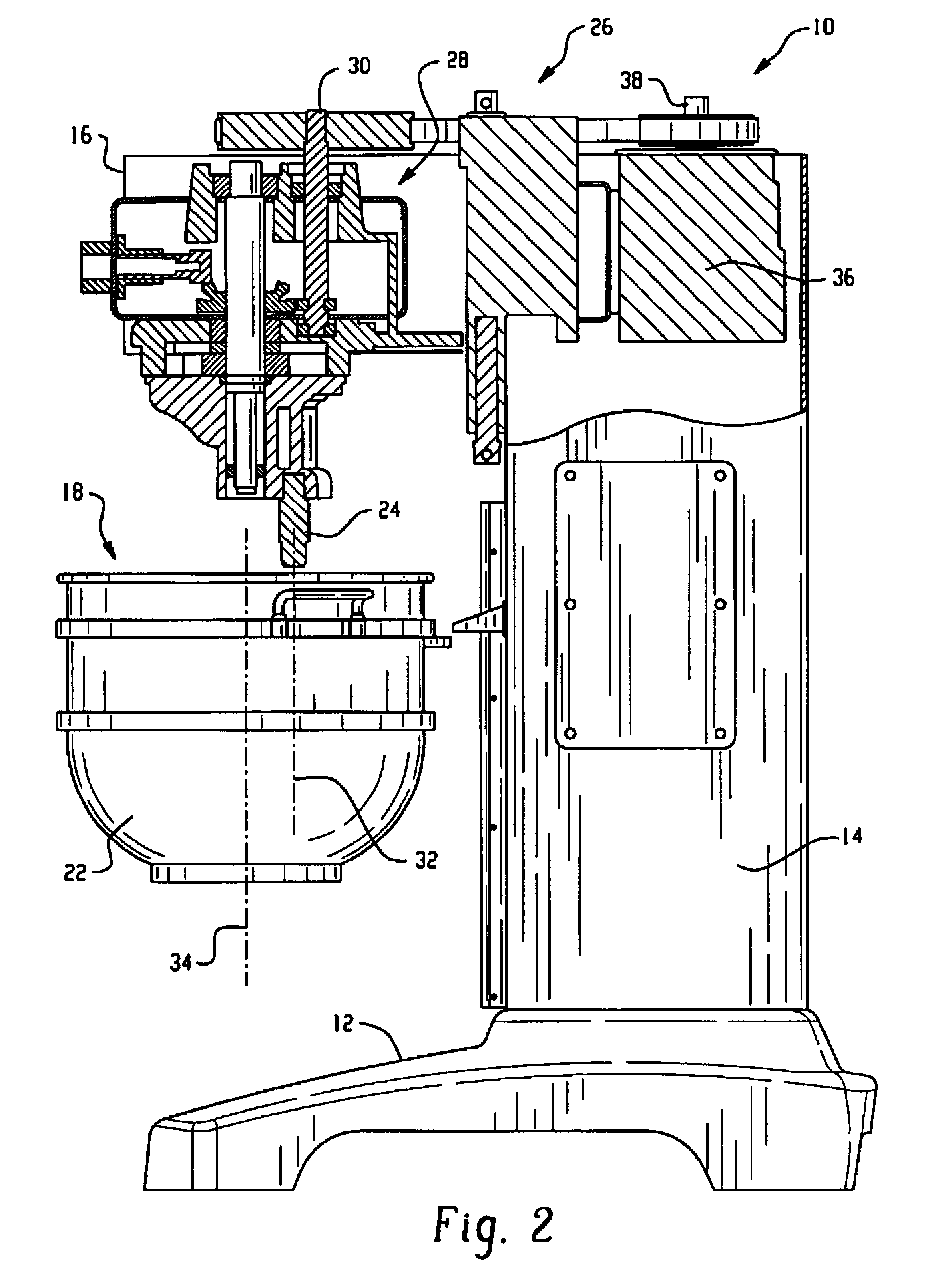
Referring to FIGS. 1-2, a mixing machine 10 is shown and includes a base 12, a mixer body 13 including a column 14 extending upward from the base 10, and a head 16 extending outward from the column 14 and over a bowl receiving location 18. The bowl receiving location 18 may be defined by a bowl receiving portion 20 of the mixer body 13, where the bowl receiving portion 20 has spaced apart curved arms 21 defining a curved shape to match the bowl 22. The head includes a downwardly extending rotatable output member 24 that can receive a mixer tool such as a flat beater, whisk or other tool. The head 16 and upper portion of the column 14 typically include a detachable cover (not shown) for enclosing the components.

The mixing machine includes a drive assembly 26 for effecting rotation of the rotatable output member 24. In the illustrated machine the drive assembly is formed in part by a gear system 28 within the head 16 and having an upwardly extending input drive shaft 30. In the case o...


PUM


Abstract

A bowl scraper is configured for attachment to a rotatable mixing machine support such that forces exerted on the bowl scraper during scraping operations hold the bowl scraper in place.

Description

TECHNICAL FIELDThe present application relates generally to mixing machines utilized for mixing food products such as cake batter, and more particularly to a mixing machine bowl scraper and related attachment system for the same.BACKGROUNDThe use of bowl scrapers in food mixing machines is known as from U.S. Pat. No. 4,946,285. The scraper is positioned to slide along the interior side of the mixing bowl to remove food product therefrom to assure more thorough mixing. The described arrangement in U.S. Pat. No. 4,946,285 requires the use of moving parts and therefore increases manufacturing costs.Accordingly, it would be advantageous to provide a mixing machine with an improved bowl scraper and associated attachment system.SUMMARYIn one aspect, in a mixing machine including a rotatable support extending from a mixer head, a connecting and support system for quickly connecting and disconnecting a bowl scraper is provided. The system includes a bowl scraper attachment arm including a t...

Claims


Application Information

Patent Timeline
IPC IPC(8): B01F15/00B01F7/16B01F7/00
CPCB01F7/00208B01F7/1605B01F2215/0427B01F2215/0026B01F27/091B01F27/805B01F2101/1805
Inventor DONTHNIER, THOMAS S.SCHNIPKE, JANICE J.
Owner PREMARK FEG L L C
Learn More